This concept sheet explains the procedures to follow to determine the focal length of a lens.
The focal point is a specific point on the main axis where incident rays parallel to the principal axis converge, or where these rays appear to come from (in the case of a diverging lens).
Depending on the type of lens, there are various techniques for determining the position of the lens’s focal point.
|
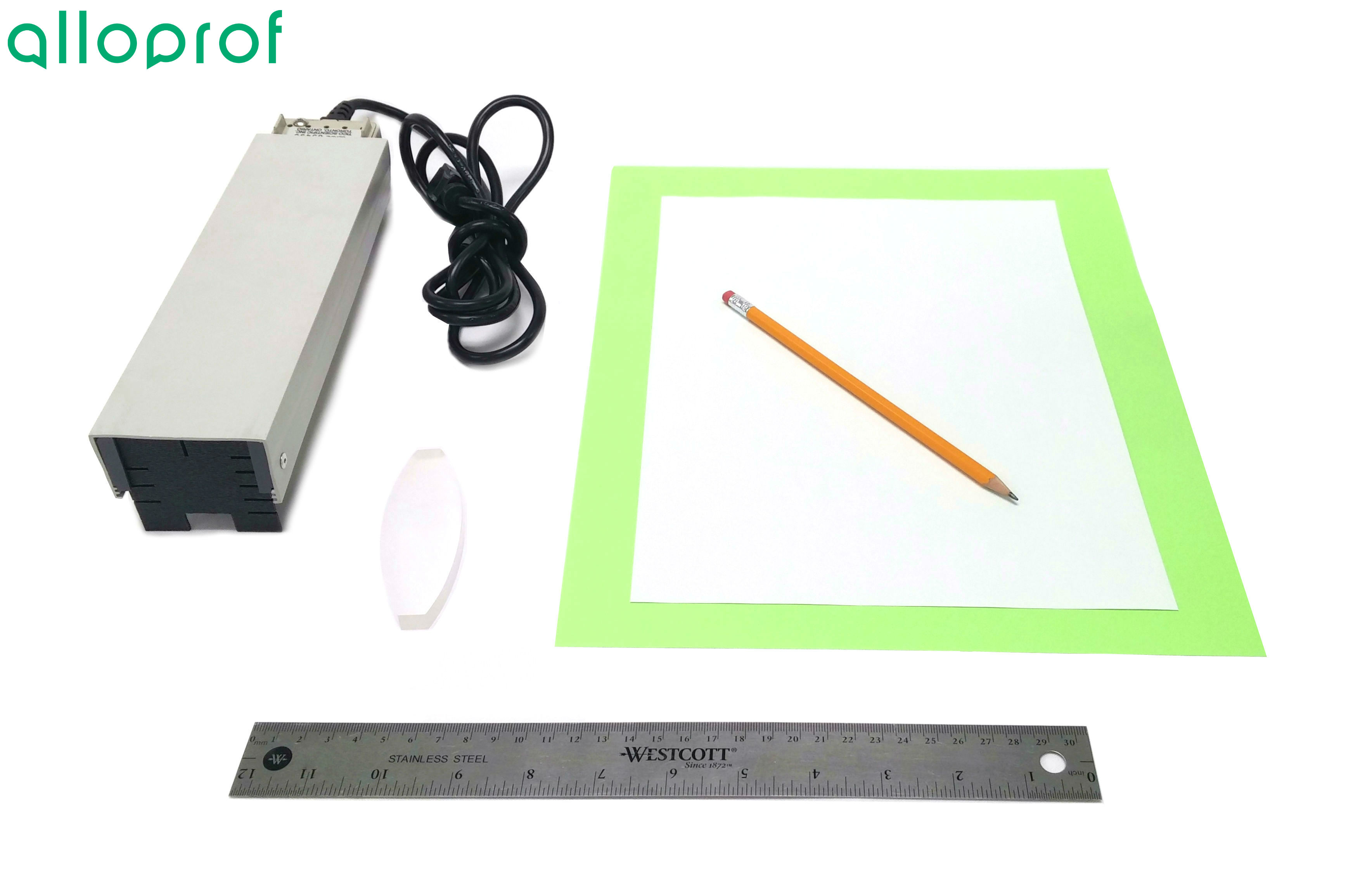 |
When using a ray box, laser rays must not be directed into the eyes of another person. Doing so could cause eye damage.
-
Draw a line in the centre of the sheet of paper.
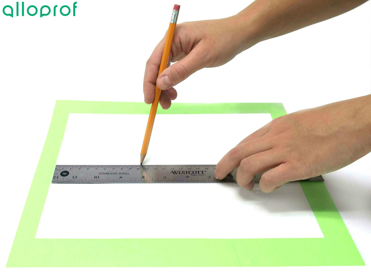
-
Lay the lens down so that the centre of the lens is over the centre of the sheet.
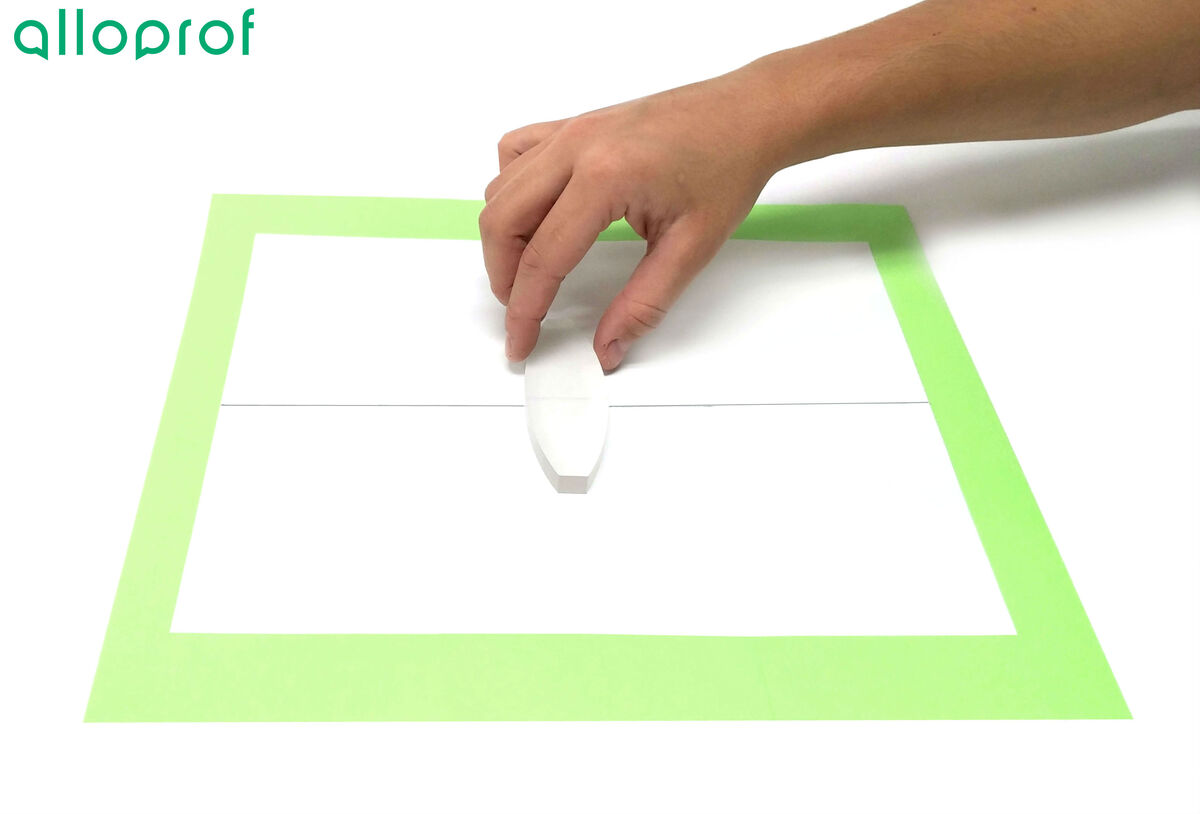
-
Trace the outline of the lens.
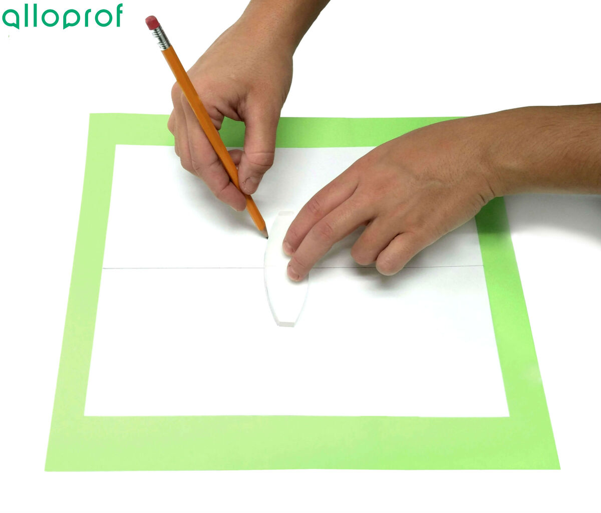
In order to see the refracted rays well, it is best to do this lab in the dark.
-
Place the raybox in front of the lens.
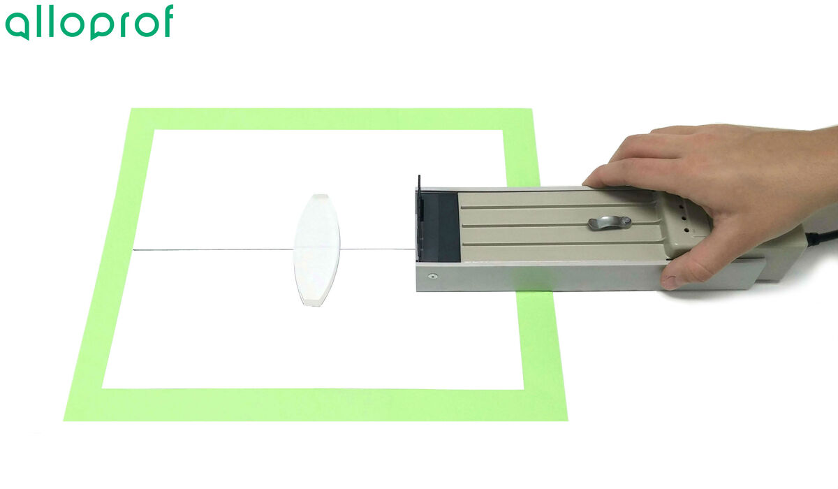
In order to see the refracted rays well, it is best to do this lab in the dark.
-
Using a three- or five-beam filter, project parallel rays onto the lens.
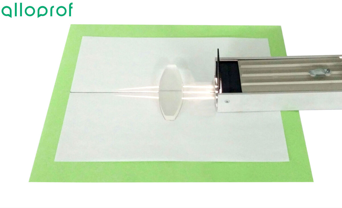
To ensure that the rays are correctly positioned, simply put the central light ray on the line drawn at the beginning. This ray should not be deflected as it passes through the lens.
-
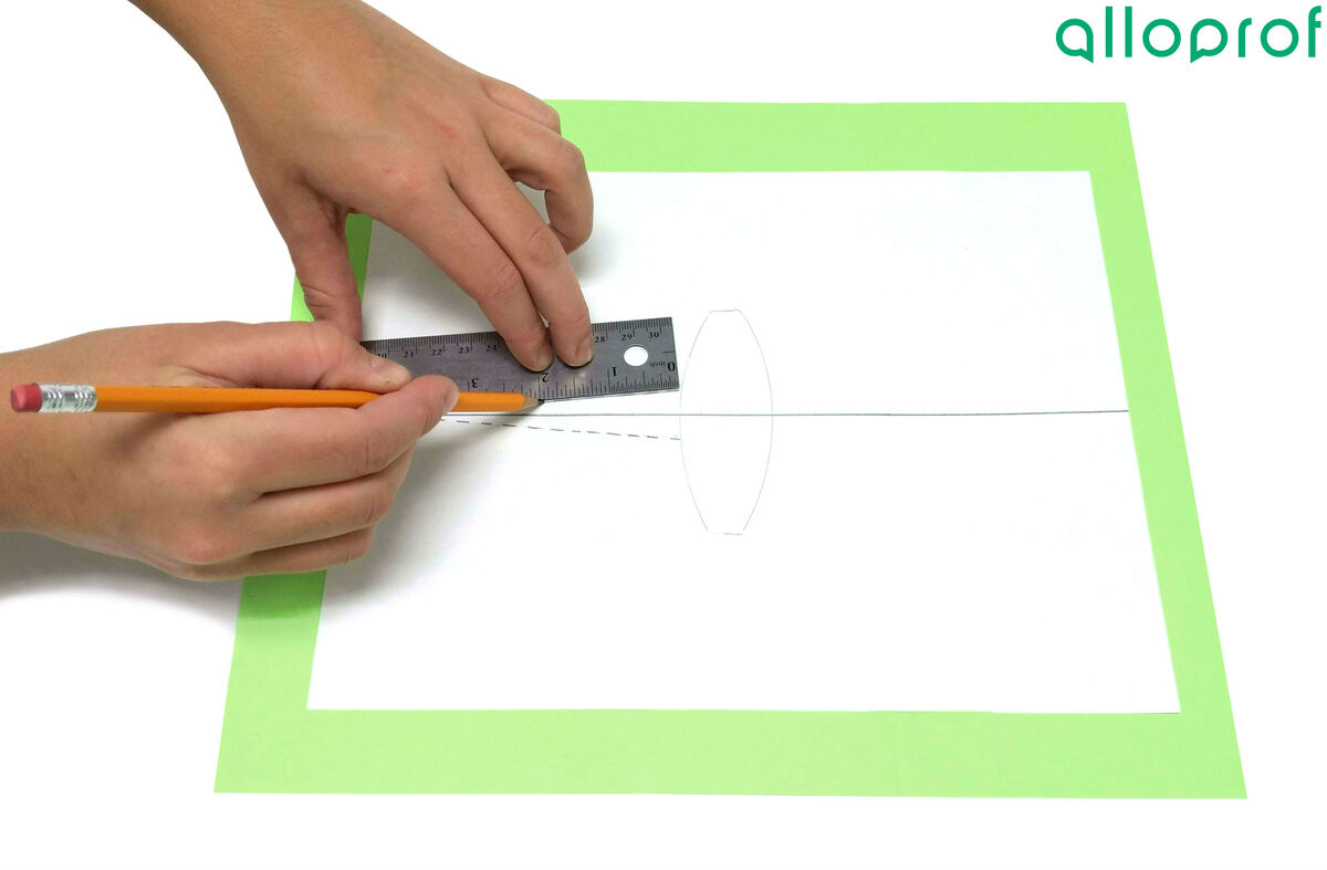
Draw a few dotted lines on the refracted rays’ path to identify the position of each light ray.
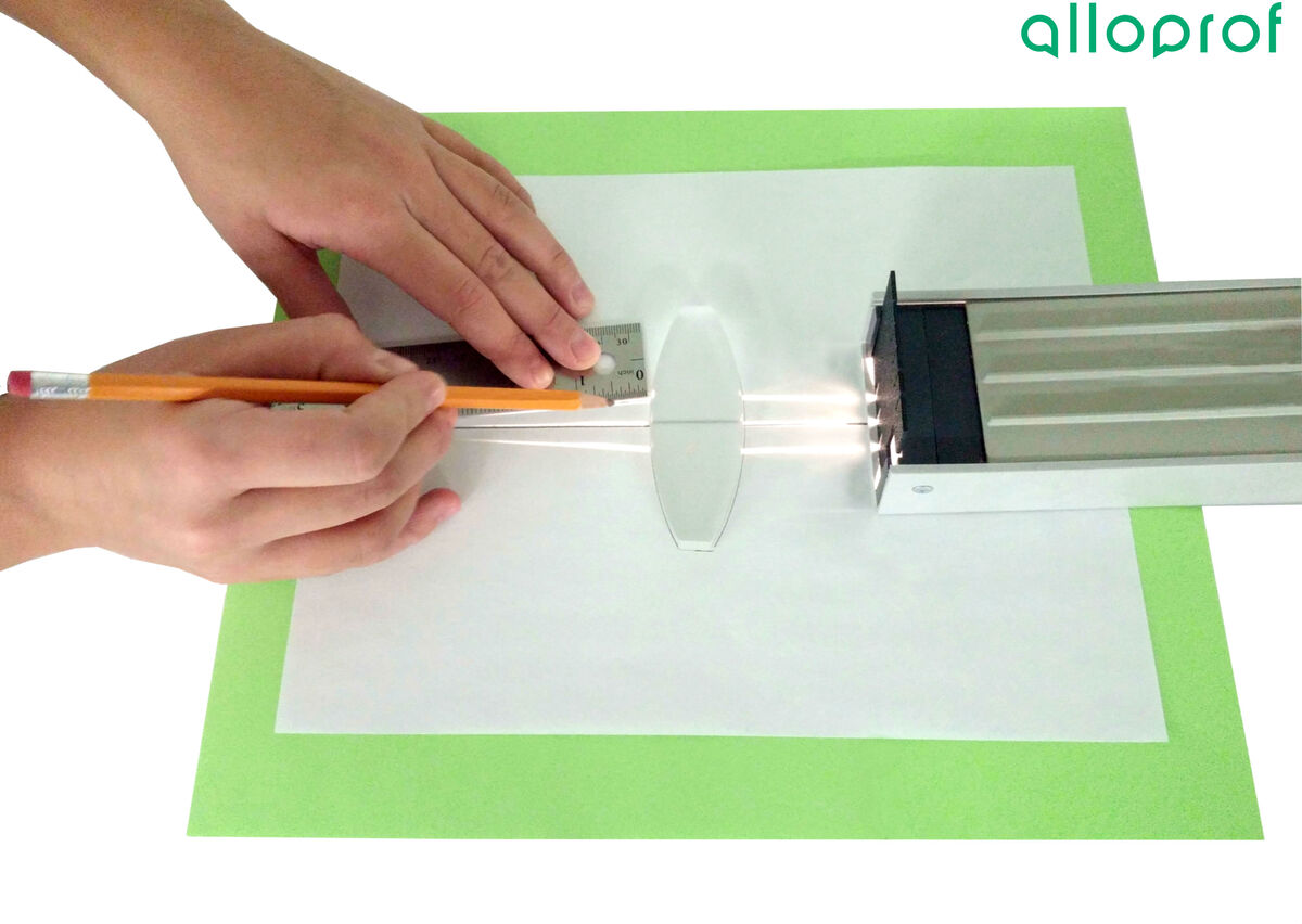
-
Remove the ray box and lens from the paper.
-
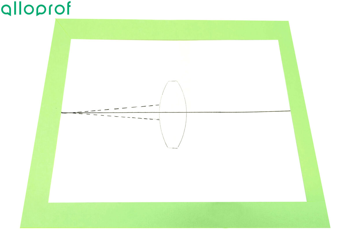
Using the draft created in the previous step, draw a line starting from the lens through the dotted lines.
-
At the intersection point between the drawn rays, add an |F| indicating the position of the focal point.

The focal length should appear on the principal axis, which is the central line used to position the lens at the beginning.
-
Put away the equipment.
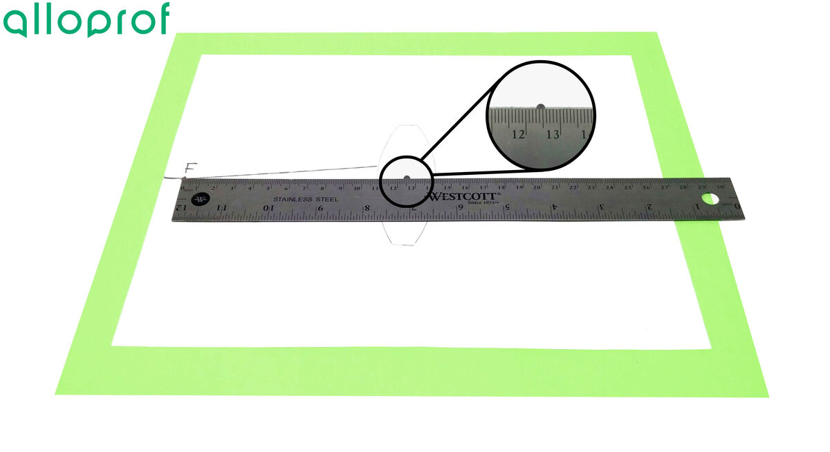
By knowing the position of the focal point, it is possible to determine the focal length of the lens used. To do this, mark the center of the lens on the sheet. Then all you have to do is measure the distance between the centre of the lens and the focal point, which is the focal length of the lens. In the example below, the measured length is |12.4\ \text{cm}.| Since the focal point of the lens is on the side opposite to the incident rays, the value of its focal length must be positive. Its focal length is therefore |12.4\ \text{cm}.|
|
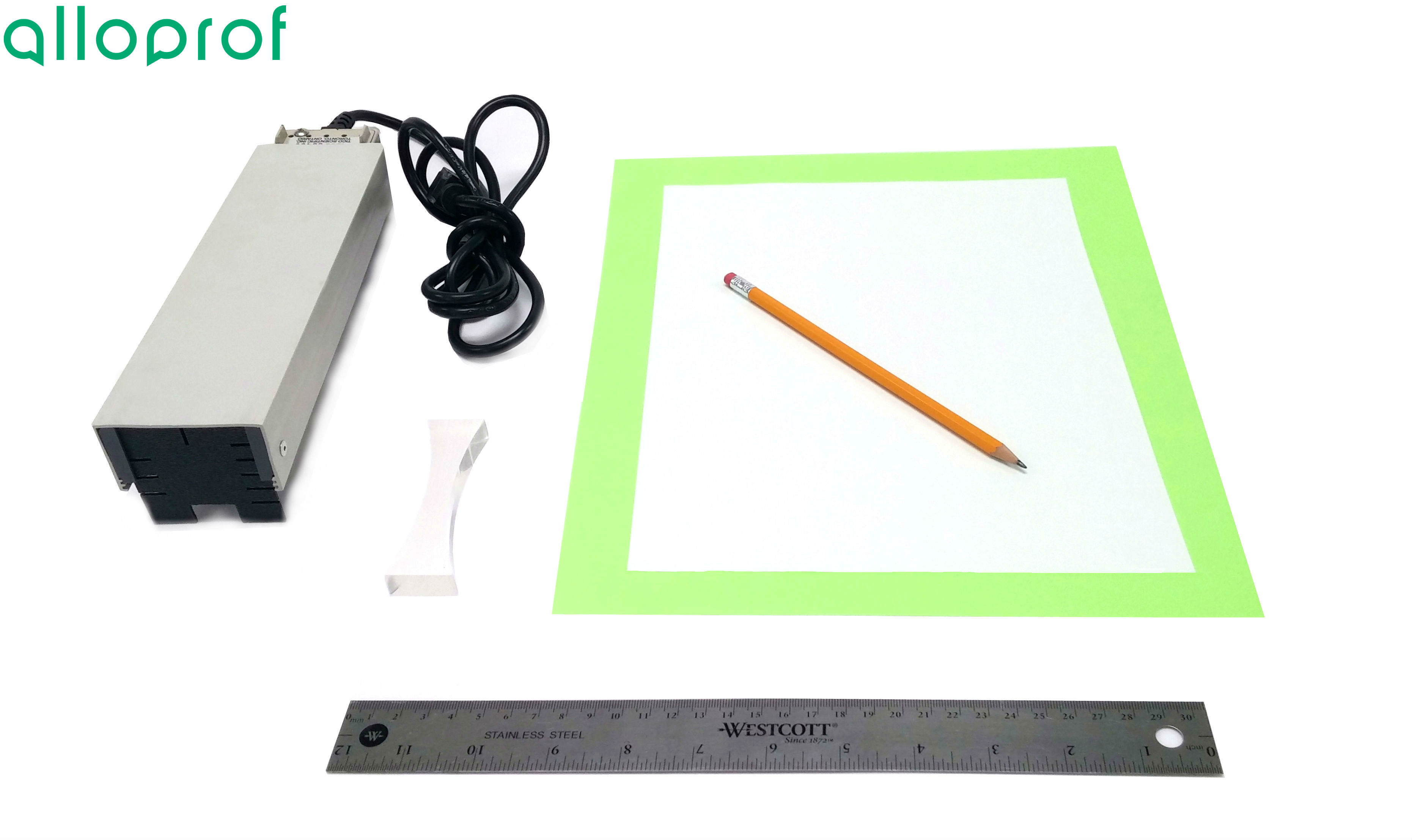 |
When using a ray box, laser rays must not be directed into the eyes of another person. Doing so could cause eye damage.
-
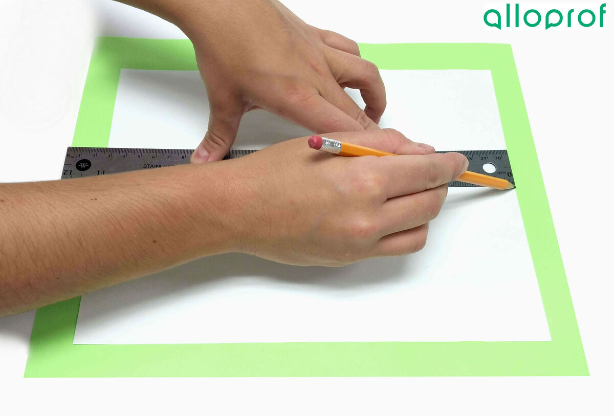
Draw a line down the centre of the sheet of paper.
-
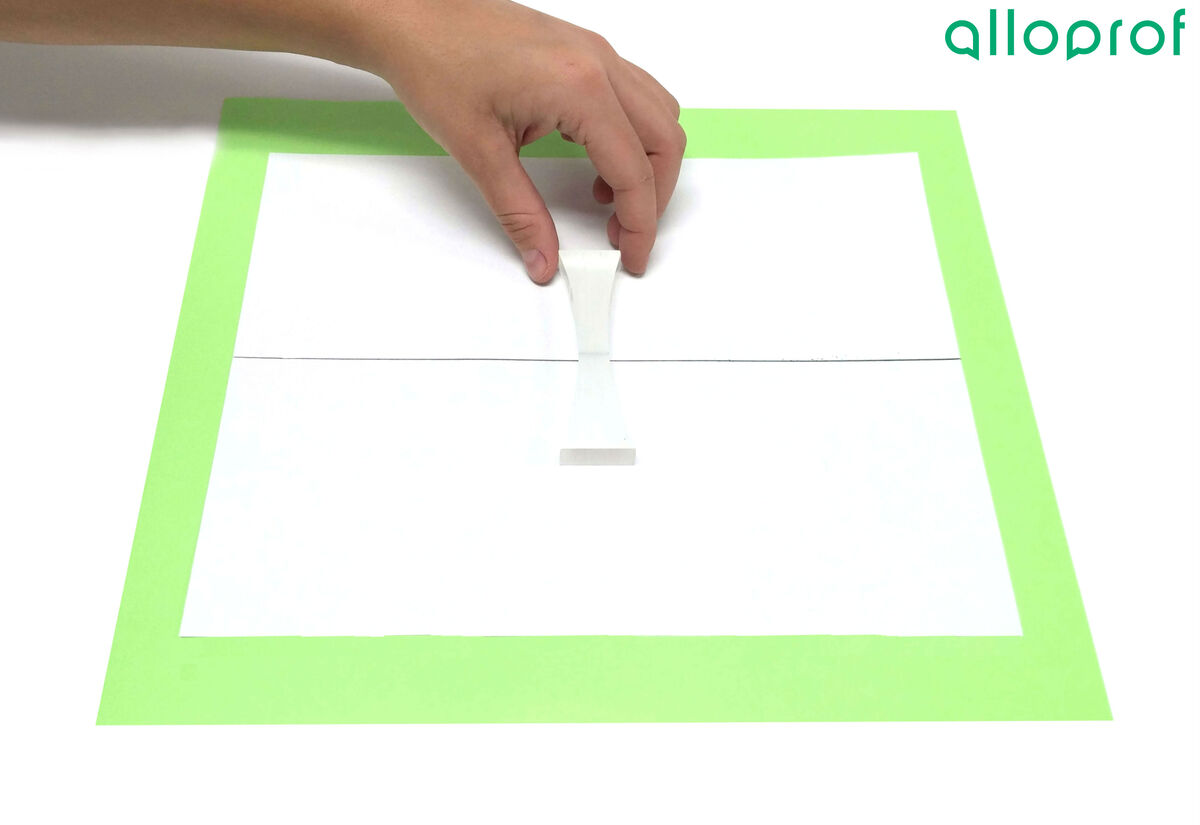
Lay the lens down so that the centre of the lens is over the centre of the sheet of paper.
-
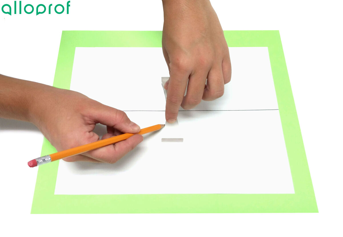
Trace the outline of the lens.
-
Place the ray box in front of the lens.
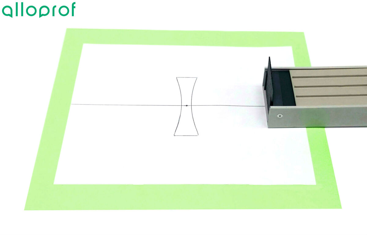
In order to see the refracted rays well, it is best to do this lab in the dark.
-
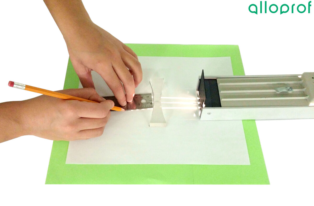
Using a three- or five-beam filter, project parallel rays onto the lens.
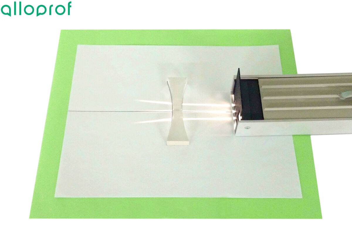
To ensure that the rays are correctly positioned, simply put the central ray on the line drawn at the beginning. This ray should not be deflected as it passes through the lens.
-
Draw a few dotted lines in the refracted rays’ paths to identify the position of each ray.
-
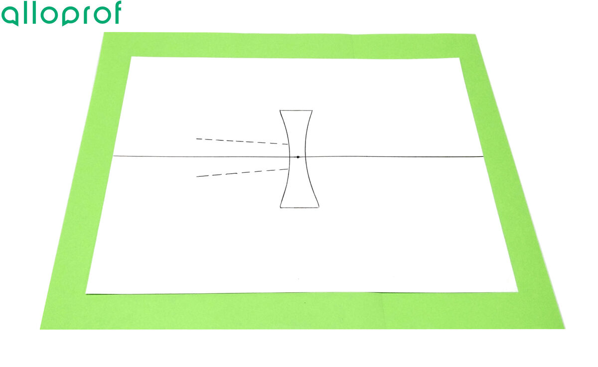
Remove the ray box and lens from the paper.
-
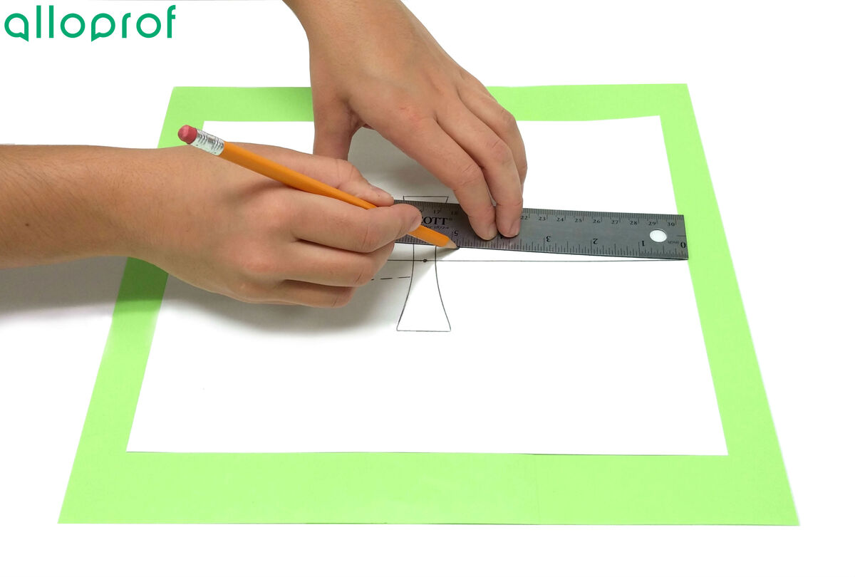
Draw a line starting from the lens through the dotted lines and extend each ray behind the lens.
-
At the intersection point between the extensions of the drawn rays, add an |F| indicating the position of the focal point.
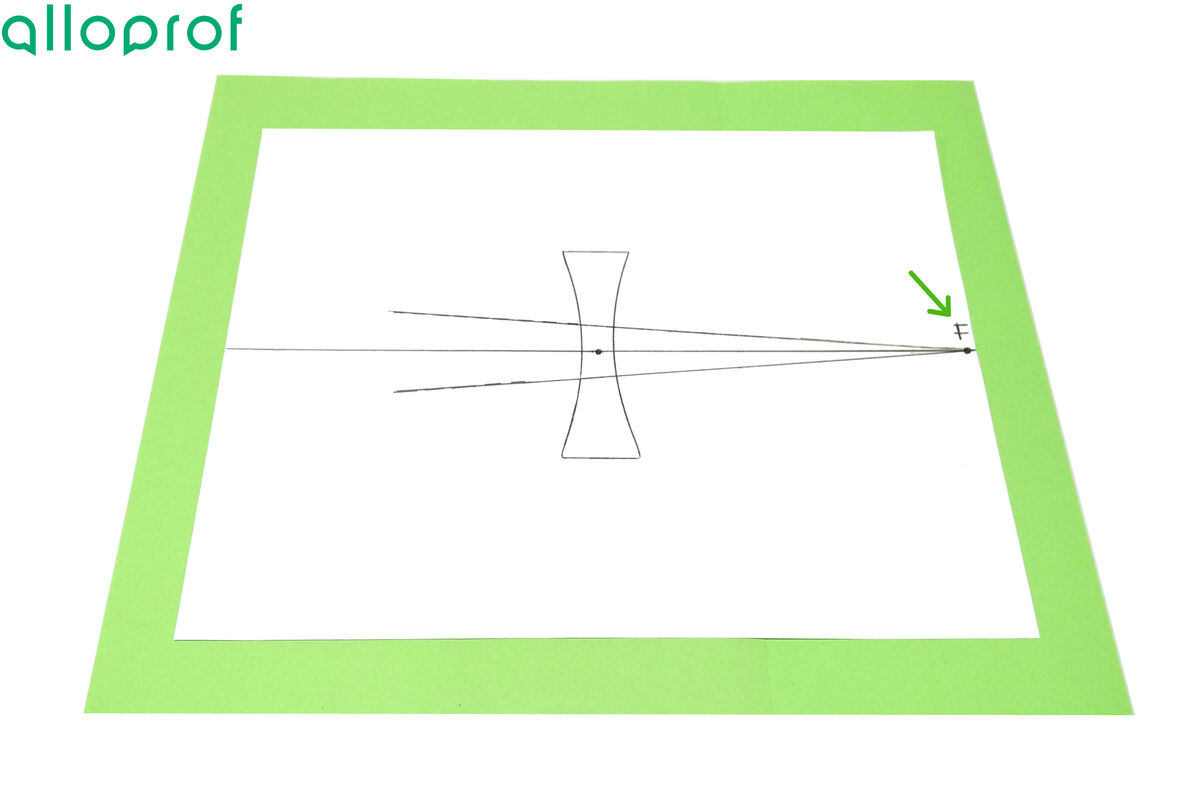
The focal point should be on the principal axis, which is the central line used to position the lens at the beginning.
-
Put away the equipment.
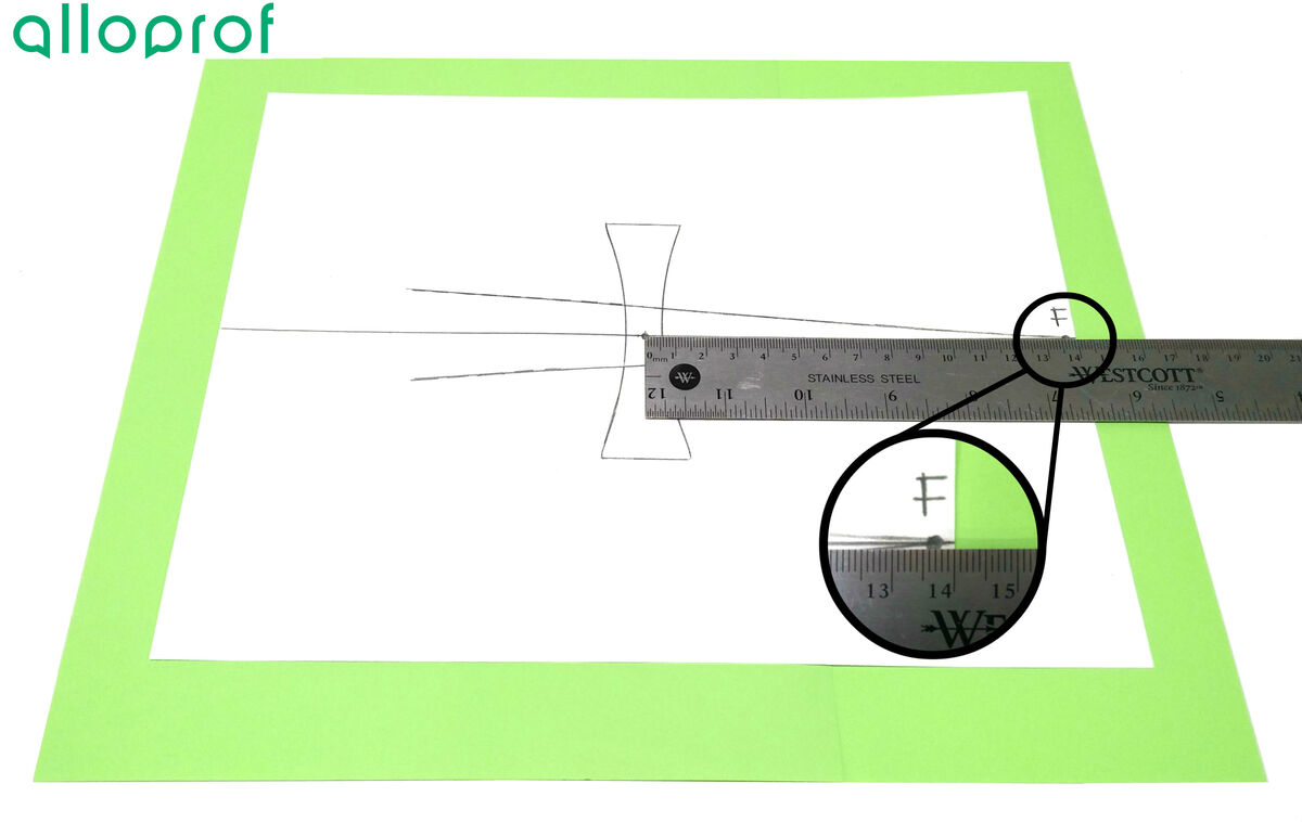
By knowing its position, it is possible to determine the focal length of the lens used. For this purpose, mark where the centre of the lens is on the sheet of paper. Then simply measure the distance between the centre of the lens and the focal point, which is the focal length of the lens. In the example below, the length measured is |13.7\ \text{cm}.| Because the focal point of the lens is on the same side as the incident rays, the value of the focal length of this lens must be negative. It is therefore |-13.7\ \text{cm}.|
|
 |
-
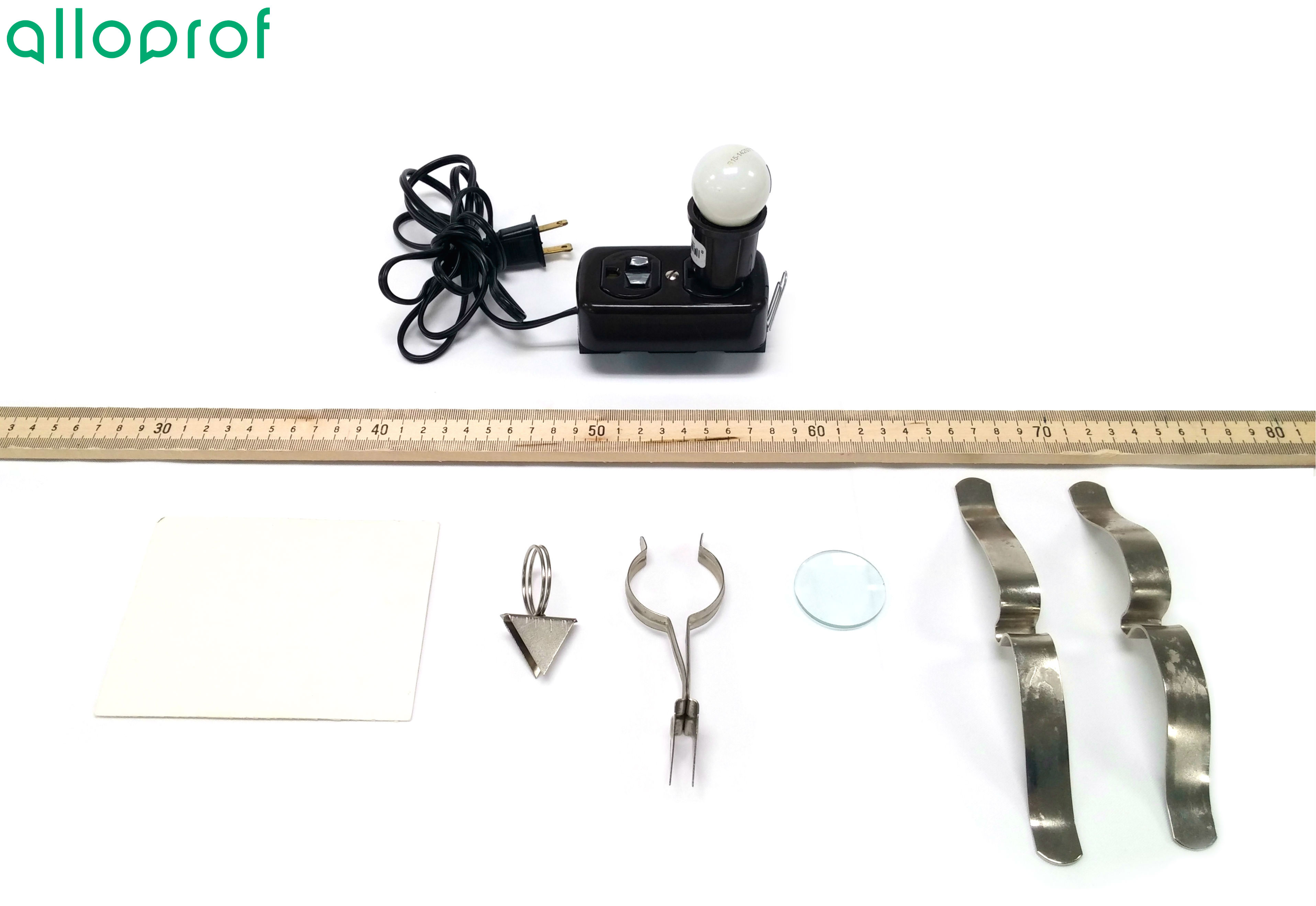
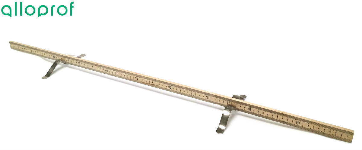
Prepare the optical bench by placing the metre stick into the bench supports.
-
Put the lens in the lens support, and place it at one end of the metre stick.
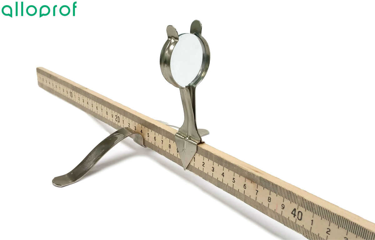
In order to make the focal length easier to read, it is better to place the support at a point corresponding to a fixed value (for example, at |1\ \text{cm}|) rather than using a decimal value (for example, at |0.4\ \text{cm}|).
-
Place a screen in a screen support, and position it behind the lens.
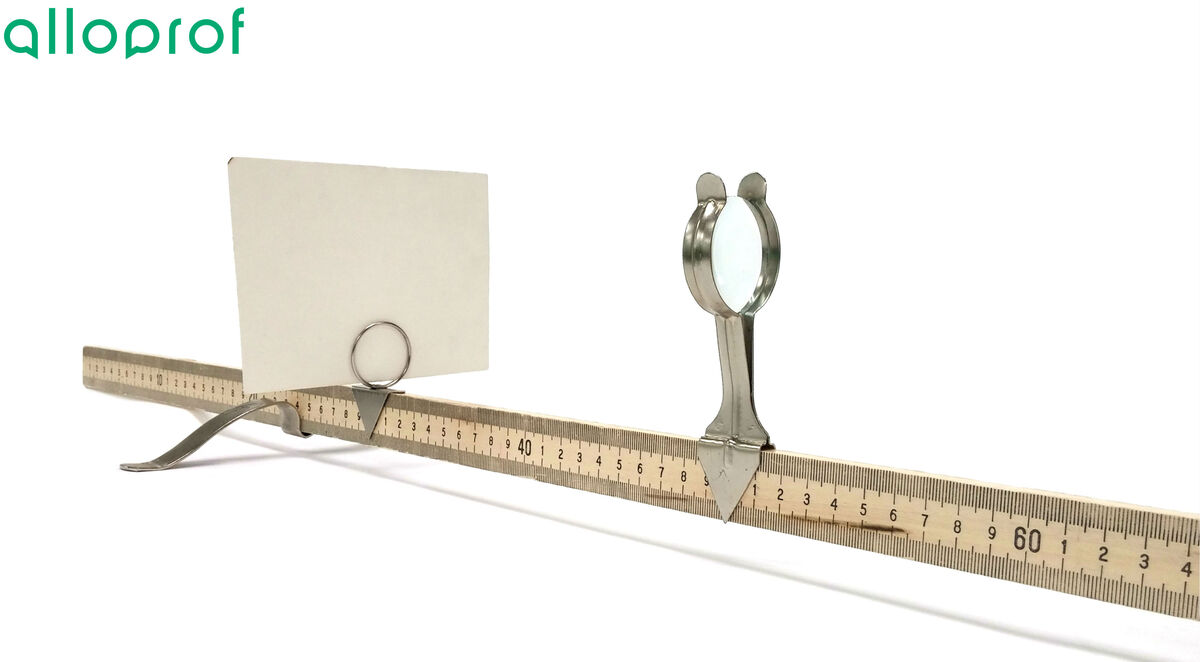
-
Position the light source as far as possible from the lens, in front of the lens.
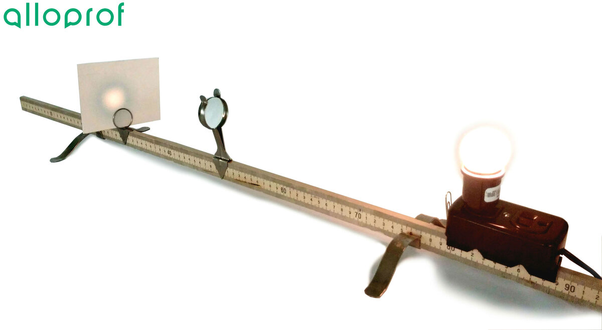
-
Move the screen forward or backward until you get a clear, sharp image. The resulting image should be bright and very small.
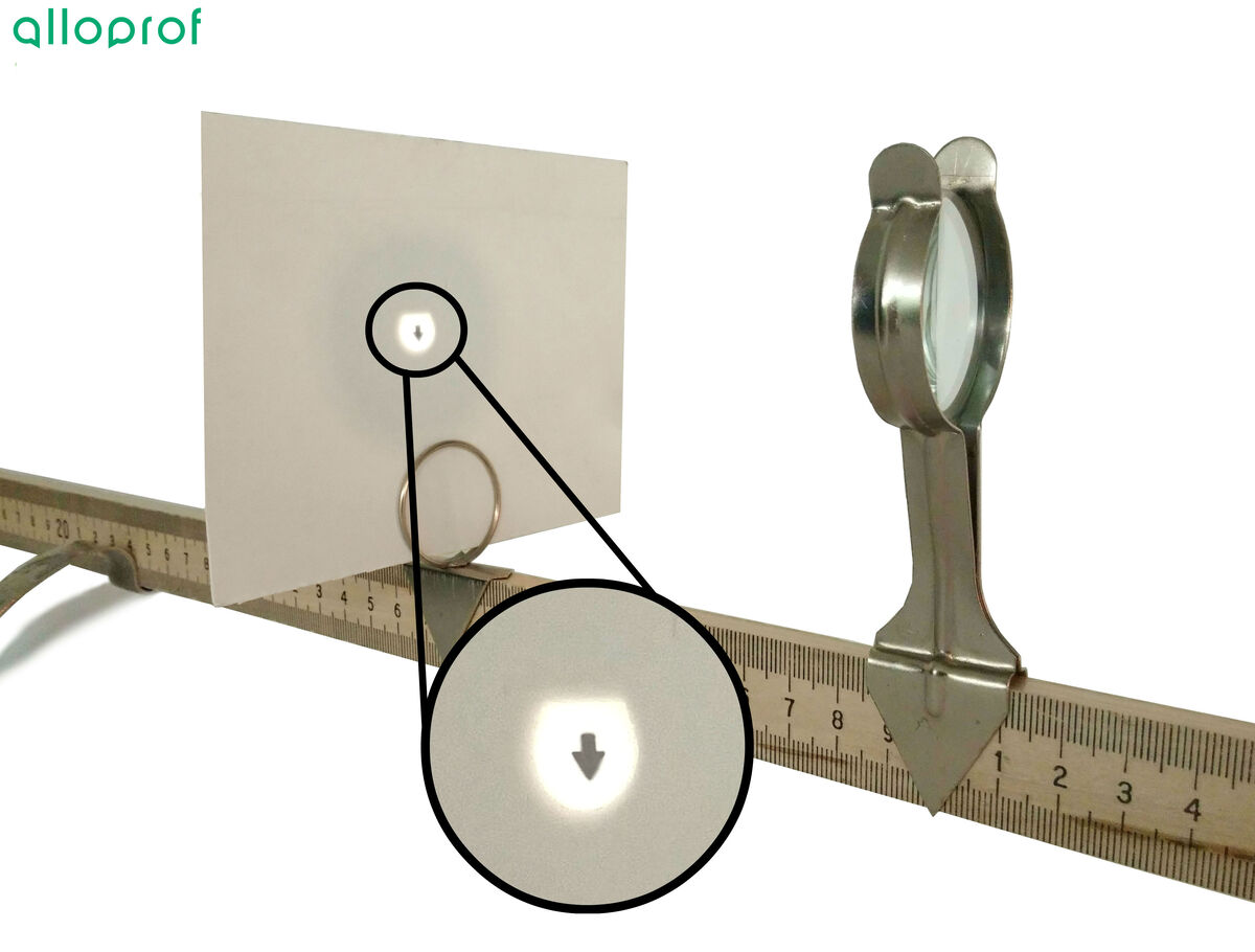
-
Measure the distance between the tip of the lens support and the tip of the screen support.
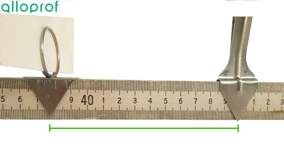
-
Put away the equipment.
The distance obtained between the two supports represents the focal length. In the example above, the focal length of the converging lens is |12.3\ \text{cm}.|
By using this method it is possible to calculate the focal length without having to draw anything. However, ensure that the image obtained on the screen is optimal. It may, therefore, be practical to redo the procedure a second time in order to validate the experimental results.
It is not possible to carry out this experimental approach with a diverging spherical lens, since this type of lens produces an image in front of the lens. The screen would then need to be placed in front of the lens, which would impede the light from reaching the lens.
However, calculating the focal length of a diverging spherical lens in a lens system would be feasible.