Kirchhoff's laws are statements that can be used to predict how the intensity of the electric current and the potential difference react in an electric circuit.
There are two laws.
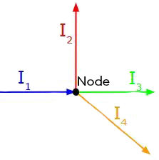
A node (or a junction) is a point in a circuit where more than two wires intersect.
The junction rule states that the sum of the current intensity |(I)| flowing into a node must be equal to the sum of the current intensity flowing out of that node.
This rule is useful only in parallel circuits, as there are no nodes in a series circuit. Therefore, in a series circuit, the current intensity is constant everywhere.
In a series circuit, the current intensity is the same no matter at which point the current is measured.
|I_{t} \text {or} I_{s} = I_{1} = I_{2} = I_{3} = ...|
In a parallel circuit, the junction rule helps to understand the behaviour of the current intensity.

The junction rule stems from the idea that no charge can be stored in the node. Therefore, in the previous diagram, the number of charges per second arriving to the node |(I_{1})| is the same as the sum of the charges per second leaving the node through each of the other three wires |(I_{2}, I_{3}, I_{4}).|
In a parallel circuit, the intensity of the current at the source is equal to the sum of the current in each branch of the circuit.
|I_{t} \text {or} I_{s} = I_{1} + I_{2} + I_{3} + ...|
The junction rule is similar to what happens in a store. If twenty customers walk into the store and pass through any of the open check-outs before exiting the store, then the number of customers who will pass through all the check-outs to exit the store will be equal to the number of customers who walked into the store.
In an electrical circuit, the number of electrical charges (customers) per second that will flow in each of the different paths (check-outs) will be equal to the number of charges per second that flowed into the circuit.
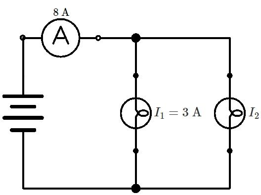
In the following circuit, what is the intensity of the current flowing in the second light bulb?

The junction rule states that the current intensity flowing into a node must equal the current flowing out of it. In the above situation, the current entering the node, which is |8 \text {A},| must be the same as the sum of the intensities flowing in the two light bulbs. ||\begin{align}I_{t}=I_{1} + I_{2} \quad \Rightarrow \quad I_{2} &=I_{t} - I_{1} \\ I_{2} &= 8 \text {A} - 3 \text {A} \\ &= 5 \text {A} \end{align}|| The intensity of the current in the second light bulb is |5 \text {A}.|
A loop is a closed course present in an electrical circuit.
The loop rule states that in an electrical circuit loop, the voltage |(V)| at the terminals of the power source is equal to the sum of the voltages at the terminals of the other components.
Only one loop can be found in a series circuit, as there is only one path through which electric charges can flow. Thus, in a series circuit, the voltage at the terminals of the source is equal to the sum of the voltages of all the elements in that circuit.
In a series circuit, the voltage at the source is equal to the sum of the voltages of all the elements in the circuit.
|V_{t} \text {or} V_{s} = V_{1} + V_{2} + V_{3} + ...|
As a comparison, we can imagine the voltage in a circuit like a delivery truck that has to deliver boxes. If it leaves the warehouse with five boxes, it will return to its starting point after delivering them. After delivering three boxes to the first address, it will be able to deliver the remaining two boxes to its second address.
The principle is similar in an electrical circuit. The electrical charges start off from the source (the warehouse) with a maximum amount of energy (the boxes) that they will lose in the different elements of the electrical circuit (the addresses).
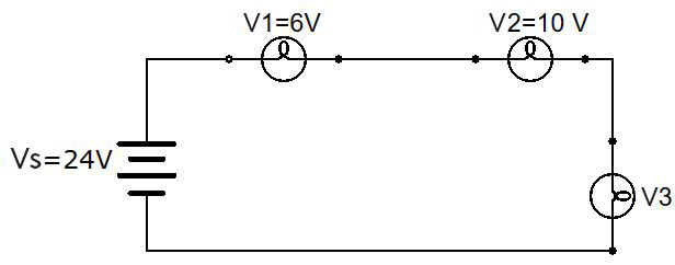
In the following circuit, what is the voltage in the third light bulb?

In a series circuit, the voltage at the source is equal to the sum of the voltages flowing in all the elements of the circuit. In the situation below, the sum of the voltages flowing in all the light bulbs must be equal to |\text {24 V}|, which is the voltage at the source. ||\begin{align}V_{s} = V_{1} + V_{2} + V_{3} \quad \Rightarrow \quad V_{3} &=V_{s} - V_{1} - V_{2} \\ V_{3} &= 24 \text { V} - 6 \text { V} - 10 \text { V} \\ &= 8 \text { V} \end{align}|| The voltage in the third light bulb is |8 \text {V}.|
In a parallel circuit, there are several loops, each of which allows current to flow through the various elements of the circuit. However, each loop is connected directly to the current source. The voltage at the source is therefore equal to the voltage in each of the elements in the circuit.
In a parallel circuit, the voltage is equal across all elements of the circuit.
|V_{t} \text {or} V_{s} = V_{1} = V_{2} = V_{3} = ...|
Pour valider ta compréhension à propos des calculs dans les circuits électriques de façon interactive, consulte la MiniRécup suivante :
