To get a general idea of what an object looks like, it is useful to have a representation that includes as many faces of the object as possible. In these situations, parallel projections tend to be used.
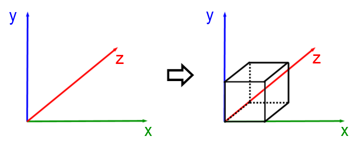
A parallel projection is a depiction of an object along three axes (one for each of the three dimensions) which meet at one point, that is at one of the vertices of the object studied.
So, in a parallel projection, each axis of a Cartesian plane is associated with a dimension of the figure: the width (the |x|-axis), length (the |y|-axis) and height (the |z|-axis). In addition, the |z|-axis generally forms an angle of |30^\circ| or |45^\circ| with the |x|-axis.

-
The edges of each axis serve as the basis for drawing the object.
-
The edges that are parallel in real life are also parallel in the plane.
There are two types of parallel projections: cavalier projections and axonometric projections.
In a cavalier projection, only the front face of the object is not distorted compared to reality. The oblique edges (called receding lines) all point in the same direction towards a vanishing point, creating an angle between |30°| and |45°|. Finally, the length of the receding lines is shorter on paper compared to reality.
To draw a solid from a cavalier perspective, follow these steps:
-
Draw the front face of the solid.
-
Trace the receding lines.
-
Draw the missing edges.
Draw a rectangular prism from a cavalier perspective.
In the following interactive animation, move the cursor from left to right to observe the stages of drawing a prism in a cavalier perspective.
Note that edges that are hidden in reality can be represented by dotted lines.
According to the scientific approach, such a perspective is defined by the oblique projection.
In an axonometric projection, only the vertical edges of the object lie in the same plane as the sheet on which it’s plotted. To draw solids in an axonometric perspective more easily, using isometric dot paper is strongly recommended. All the lengths drawn in this representation are proportional to their measurements in reality.
To draw a solid in axonometric perspective, follow these steps:
-
Draw the first height vertically.
-
Draw the receding lines on both sides of the first line.
-
Draw the missing edges.
Draw a rectangular prism from an axonometric perspective.
In the following animation, move the cursor from left to right to observe the stages of drawing the axonometric projection of a prism.
Note that edges that are not visible in reality may be represented by dotted lines. In addition, the edges which are congruent and parallel in reality remain so when represented on paper.
Once again, we can observe the same kind of properties in an isometric projection in science.
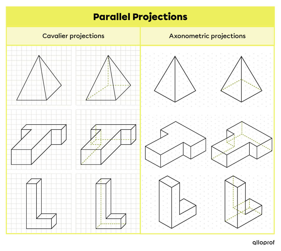
In the following table, observe three models of solids which are depicted with cavalier and axonometric projections. Each model is depicted both opaque and translucent (using dotted lines to show hidden lines).
