Dimensioning and dimensional tolerance are essential information for the manufacturing of an object since they specify its measurements. In technical drawing, when developing a manufacturing drawing to produce an object, it is important to ensure that this information is displayed.
Dimensioning is the indication of the real dimensions and the position of the different elements of an object on a technical drawing.
In order to allow the manufacturing of a part, a technical drawing, more precisely a detail drawing, must provide detailed information concerning the shape and dimensions of this part. These measurements are indicated by means of dimensioning.
The dimensions indicated on the drawing correspond to the actual dimensions of the part to be built, regardless of the scale used. By convention, they are always expressed in millimetres, unless otherwise specified.
Dimensioning is used to indicate specific information on a technical drawing:
-
the dimensions of the object (length, height, depth);
-
the measurement of angles;
-
the measurement of the diameter and radius of a curve or circle;
-
the location of various elements on the object.
Certain basic lines are used for dimensioning, namely dimension lines, extension lines, and leader lines.
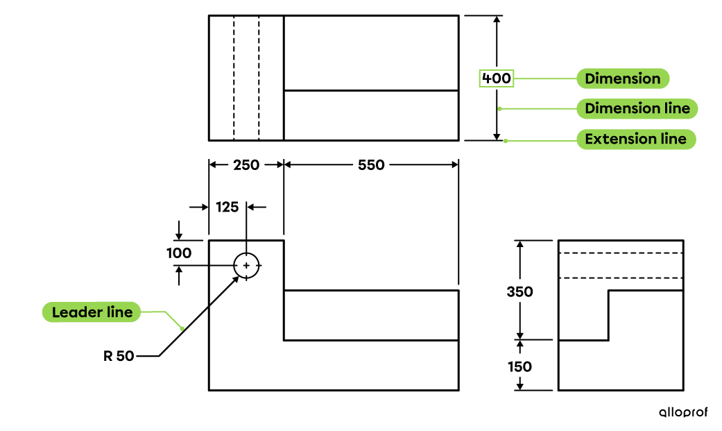
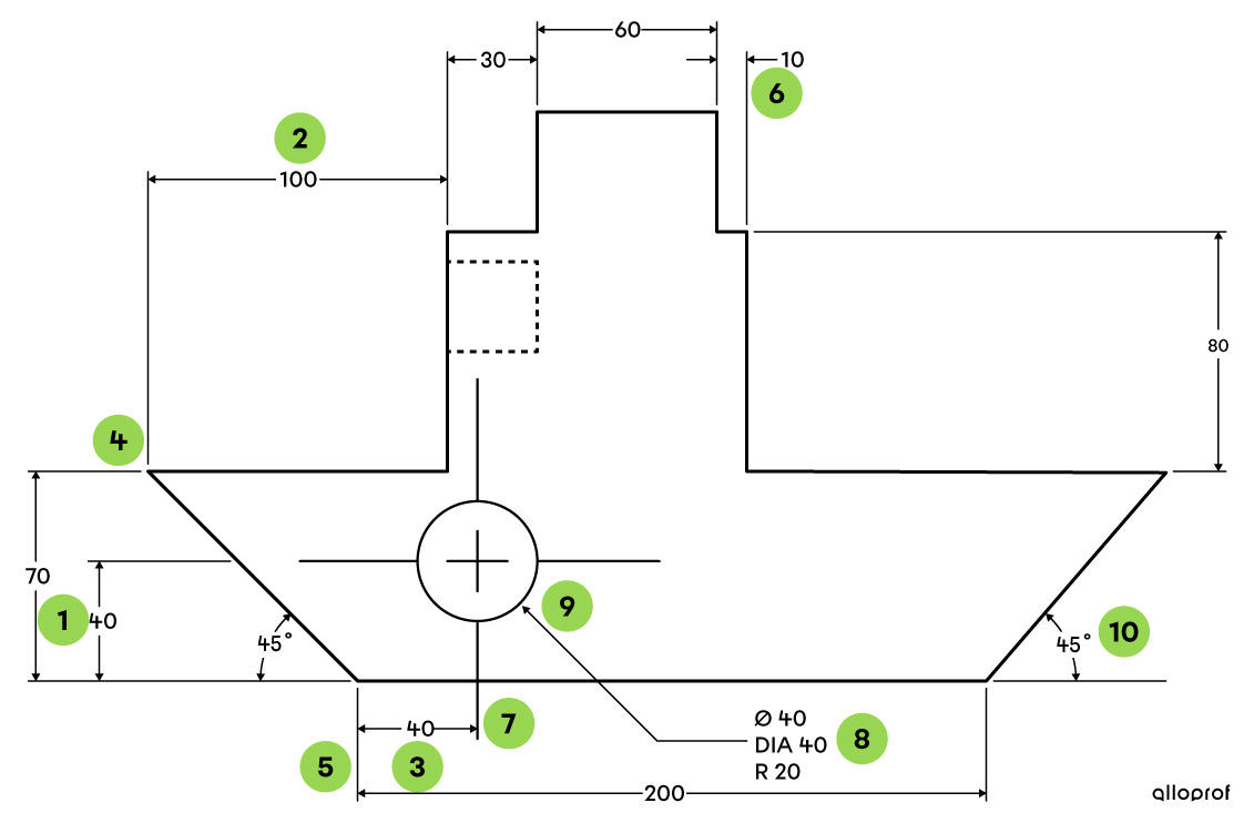
In technical drawing, precise rules must be observed when representing the dimensions of an object. Here is an example:
-
A space of at least 10 mm must separate a dimension line and the side of the object or another dimension line.
-
Dimension lines should always be outside the object.
-
The shorter dimension lines are placed in front of the longer ones, near the sides of the object.
-
The extension lines are perpendicular to the dimension lines and start 2 mm from the side of the object. They also exceed the ends of the dimension lines by 2 mm.
-
A single extension line can be used for more than one dimension.
-
If the space between the extension lines is too small to write the dimension, the arrows are then placed outside these lines with the dimension value.
-
A centre line can be used as an extension line if it extends beyond the outlines of the object.
-
The dimensions used to identify the radius of a circle are displayed with an R in front of their value. When dimensioning the diameter of a circle, the dimension is preceded by the symbol ⊘ or the letters DIA.
-
Leader lines are oriented at 45° and point to the centre of the circles.
-
The dimensioning of the angles is done by means of curved dimension lines.
Certain things should be avoided when dimensioning:
-
the dimension lines must not intersect;
-
hidden contour line measurements should not be dimensioned;
-
the dimensions that can be calculated using the others are not indicated in order to have a cleaner drawing.
Functional dimensioning provides the dimensions relating to the operation of a technical object.
Functional dimensioning provides details concerning the dimensions of the parts to be built to ensure the proper operation of the object. It provides sufficient space between the different parts of an object. This space is called clearance and therefore allows the different types of mechanical motion.
To carry out the functional dimensioning of an object, its operation should be analyzed beforehand.
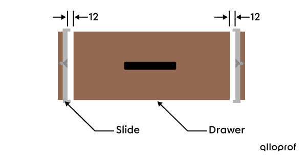
Functional dimensioning indicates the space to be provided between a drawer and the slide in which it is fitted so that it can open and close properly.
In a technical drawing, dimensional tolerance is an indication added to the dimensions. It specifies the maximum difference between the measurement indicated on the drawing and the actual measurement of a part.
Dimensioning indicates the dimensions of an object for its manufacture. However, it is almost impossible to build a part observing the exact measurements taken from the drawing. We therefore tolerate a margin of error for the dimensions of the parts to be built. This is called dimensional tolerance. It is therefore the acceptable degree of inaccuracy that does not prevent the assembly or operation of the object.
When tolerance values vary on the same object, these are generally indicated after the dimension value. However, if all the dimensions of a technical drawing have the same tolerance value, this value is indicated in the title block, an area of the sheet where the information concerning the drawing is put.
In industry, dimensional tolerance affects production costs. Indeed, the lower the tolerance, the higher the production cost. Manufacturing parts with low tolerance requires more accurate equipment. On the other hand, the part produced will be of better quality. For example, the manufacturing of a spaceship will involve a much lower tolerance than that allowed for building a pen.
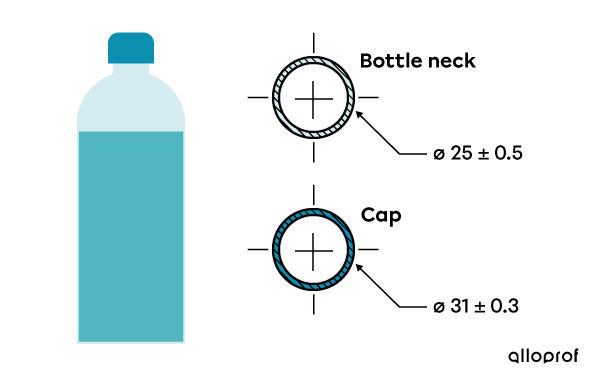
The cap of a water bottle should have the correct measurements so that it can be easily screwed onto the neck without getting stuck or being too loose. On the technical drawing, the acceptable deviation between the measurements is indicated for the neck and for the cap.
Thus, the neck of the bottle must have a diameter between 24.5 and 25.5 mm. In fact, the diameter of the neck is 25 mm, but a deviation of plus or minus 0.5 mm is acceptable. As for the cap, its diameter is 31 mm, but a difference of more or less 3 mm is tolerated. Thus, the measurement of the cap should be between 30.7 and 31.3 mm. If the dimensional tolerances of the two parts are not met, they will not fit together properly during assembly.
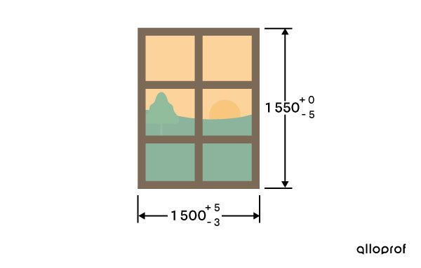
For the manufacture of the following window, the height measurement is 1550 mm. This measurement cannot be larger, but it could be up to 5 mm less. On the other hand, the measurement of the width of the window must be 1500 mm, but it could be 5 mm more or 3 mm less.
