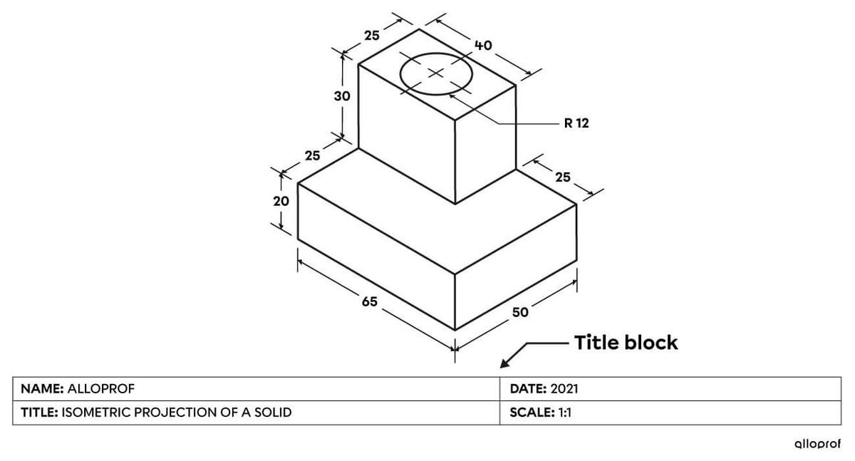
A technical drawing is a representation that is made using standardized rules. It illustrates the characteristics of a technological object necessary for its manufacture.
A technical drawing serves as a reference for everyone involved in building an object. It contains all the important details, such as dimensions, shapes and the scale used.
Technical drawings can be made on the computer or by hand. The process of creating a drawing using software is called computer-aided drawing or computer-aided design (CAD). When technical drawings are done by hand, precise instruments help with drawing geometric lines.
It is important that everyone involved in the object’s manufacturing process can read and analyze the drawing. For this reason, specific standards are used when creating a technical drawing. The interpretation of the design must be consistent everywhere around the world. These standards include the use of basic lines.
The following elements are useful in the creation of technical drawings:
A sketch is a quick drawing of the essential characteristics of an object, without using drawing instruments.
Having sketches is helpful before making a technical drawing, but it is important to distinguish between the two. On a sketch, the scale and dimensions of the object are not perfect. It is a freehand draft of the object being designed. The sketch is made first, before the technical drawing, and can be used as a reference.
The table below explains the difference between sketches and technical drawings.
| Sketch | Technical drawing | |
|---|---|---|
| Function | Serves as an outline to quickly show an idea. | Is made with precision and contains all the information necessary to manufacture an object. |
| Design process | Is drawn freehand without using drawing instruments. | Is drawn using drawing instruments or software for more accuracy. |
| Compliance with dimensions |
Is not made to scale, but the proportions of the represented object are as close as possible to reality. The conventions of technical drawing (basic lines, projections) are generally used. |
Is made to scale: the precise proportions of the object are represented. All the conventions of technical drawing are used. |
| Example |  |
 |
Technical drawings must include all the necessary information about the object being built. Depending on what information is being communicated, it is important to choose the most appropriate type of engineering drawing.
An object’s technical drawing can be made using various types of projections, allowing the observer to see it from different two- or three-dimensional points of view. By picking the right projections, it is easier to visualize an object's shape, details and measurements. Here are different types of projections:
The designers of an object’s technical drawing must also add all the information needed to manufacture it, including the full dimensioning, the dimensional tolerances and the scale used in the drawing. It is also possible to show cross-sections or sections of the object so that internal details are visible. Finally, an object’s development (net) can be shown to make it easier to manufacture by cambering (or bending).
The title block is a box at the bottom of the drafting design sheet that includes information about an object’s technical drawing.
The title block provides information about the drawing and the part being made. It is particularly useful for archiving and classifying technical drawings.
In general, the title block is a rectangle located below the representation of the object on the drafting design sheet. It may include:
-
the name of the part or object
-
the scale used
-
the designer’s name
-
the type of projection used
-
the date of the last change made to the drawing
-
the dimensional tolerance, if it is the same for all measurements
