Engineering drawings are necessary for analyzing, manufacturing and assembling objects.
An engineering drawing, sometimes called a manufacturing drawing, is a technical drawing with specific information for analyzing, manufacturing or assembling an object.
Depending on the information to be communicated, one type of engineering drawing can be chosen over another. Depending on the situation, certain projection types used in technical drawings are more useful than others. There are 3 types of engineering drawings.
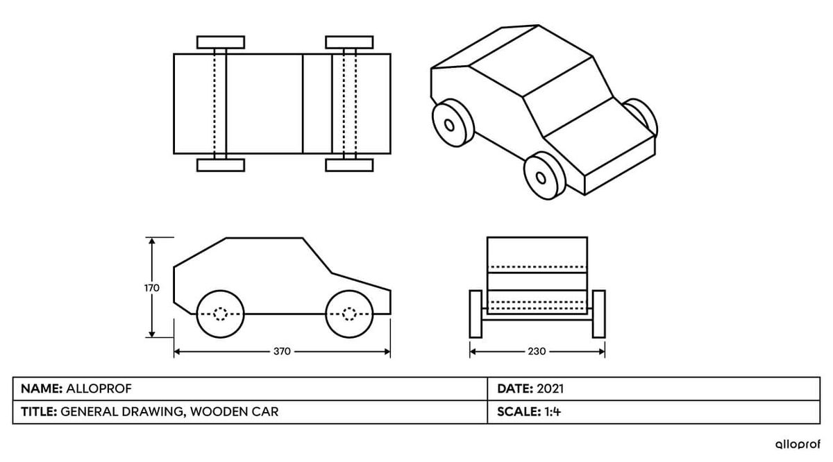
A general drawing, sometimes called a general arrangement, shows the overall appearance of an object.
To analyze an object in order to manufacture it, it is helpful to refer to a general drawing showing its overall appearance, including its shapes, its parts and their positions. To do this, multiview projections and isometric projections are used with some measurements added to better visualize the object’s characteristics.
When developing a wooden car design, the first step is to imagine what the object will look like. In the following example, the wooden car’s configuration is represented in a general drawing using multiview projections and isometric projections.

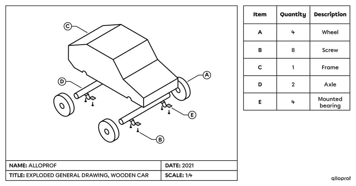
An exploded general drawing shows all the parts of an object separate from one another.
An exploded general drawing is used when several parts are combined to form a single object. This type of drawing is commonly found in instruction manuals for objects that need to be assembled, like a piece of furniture. Isometric projections are frequently used to show the parts separately and indicate how they are arranged. This type of drawing usually includes a table showing the name and number of each part in the drawing.
In the following example, an isometric projection is used to produce an exploded general drawing showing all the parts that need to be assembled to build a wooden car.

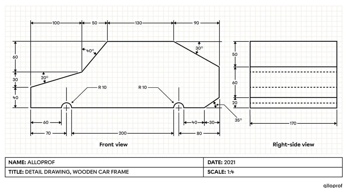
A detail drawing is a drawing that provides all the information required to manufacture a part or object.
When it is time to manufacture a part, a detail drawing must be developed in order to show all the elements required to manufacture it and to make sure it works properly. The detail drawing is made using multiview projection techniques, along with dimensioning and dimensional tolerances.
In the following example, a multiview projection is used to produce a detail drawing of a wooden car frame. All the measurements required to manufacture it are included.
