Motion transformation systems are systems that change the type of motion between the driver component and driven component.
Motion transformation is a complex mechanical function, since it is performed by a system, which is a set of components. It changes the motion type between one component of the system and another. Therefore, the rotation of the driver component (or driving unit) can drive the rectilinear translation of the driven component (or receiving unit). The reverse is also possible.
There are five motion transformation systems.
|
System name (Click on the links below) |
Description | Reversibility |
|---|---|---|
| Screw gear system |
Depending on the type of the screw gear system, either rotating the screw drives the rectilinear translation of the nut, or rotating the nut drives the rectilinear translation of the screw. | Irreversible |
| Connecting rod and crank systems |
Through the connecting rod, the rotation of the crank drives the rectilinear translation of a piston or vice versa. | Reversible |
| Rack and pinion systems |
Rotating the pinion drives the rectilinear translation of the rack, or vice versa. | Reversible |
| Worm and rack systems |
Rotating the worm drives the rectilinear translation of the rack. | Irreversible |
Cam and roller (cam and follower) systems  |
Rotating the cam drives the rectilinear translation of the roller or follower. | Irreversible |
Screw gear systems are used to transform rotational motion into bidirectional rectilinear translational motion by combining the movements of a screw and a nut.

There are two types of screw gear systems.
-
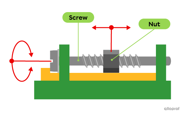
In some systems, the screw is the driver component and the nut is the driven component. The motion is transformed when the rotating screw drives the rectilinear translation of the nut.
-
In other systems, the nut is the driver component and the screw is the driven component. The motion is transformed when the rotation nut drives the rectilinear translation of the screw.
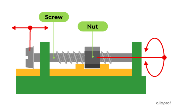
This system is irreversible. The driven component cannot become the driver component. In both types of screw gear systems explained above, the rotation of the driver component always drives the translation of the driven component. Reversing the motion transformation is impossible. It is impossible to initiate the operation of this system by activating the component that is normally driven: it will not move and will not make the other component rotate. The system simply jams.
| Advantages | Disadvantages |
|---|---|
|
|
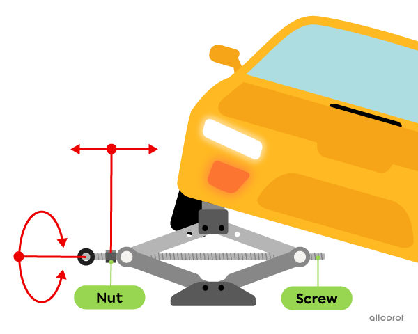
In a car jack, rotating the screw enables the rectilinear translation of the nut. This causes the two arms of the jack to rise, lifting the vehicle up.
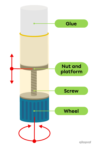
In a glue stick, the rotation of the wheel linked to the screw enables the rectilinear translation of the nut. Because the nut is attached to the platform that supports the glue, the glue is pushed out of the stick.
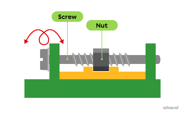
Some screw gear systems are not motion transformation systems. In these cases, one of the components moves in a helical motion while the other component is stationary.
In this system, the screw is the driver component, and it moves inside a stationary nut. The screw is guided in a helical motion by the nut.
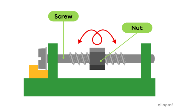
In this system, the nut is the driver component and it moves along a stationary screw. The screw guides the helical motion of the nut.
Connecting rod and crank systems transform rotational motion into bidirectional rectilinear translational motion, and vice versa.

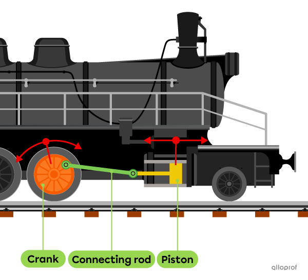
In this system, the connecting rod is the stiff rod connected at both ends by a pivot, or rotating, link. One end is linked to a part that undergoes rectilinear translation, like a piston or slider. The other end is linked to the crank, which is a round part that rotates. It is important for the connecting rod to be in contact with the crank so that the motion can be transmitted in the system. The connecting rod and crank system transforms rotation into reciprocating translation, in other words, a rectilinear back-and-forth motion.
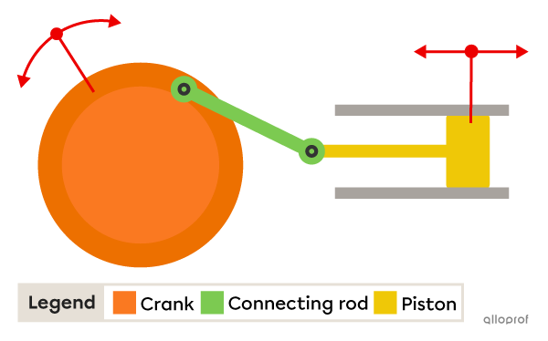
Usually, motion is initiated by rotating the crank. The crank then drives the reciprocating rectilinear translation of the connecting rod. However, the connecting rod can also serve as a driver component in some systems. This makes the system reversible, because either component can be the driver.
It is also worth noting that the connecting rod becomes an intermediate component if it transmits a rectilinear translation to another part, such as a piston.
| Advantage | Disadvantages |
|---|---|
|
|
A connecting rod and crank system links a steam locomotive’s wheels. When water is heated in the boiler, the generated steam pushes on a piston linked to the connecting rod. The rectilinear translational motion of the connecting rod is transformed into the rotation of the crank, which is attached to the wheel.
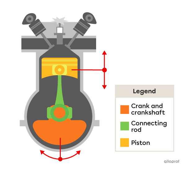
The connecting rod and crank system plays an important role in combustion engines. The piston is linked to the connecting rod. The connecting rod is linked to the crank, which is attached to the crankshaft. As the piston rises, it compresses the fuel mixture in the cylinder and drives the rotation of the crank.
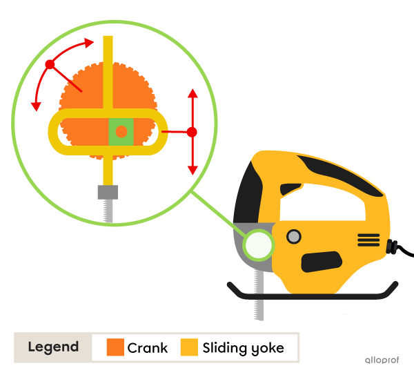
Jigsaws use a system called a Scotch yoke.
In this case, the blade is attached to the sliding yoke. As the crank rotates, the translation of the sliding yoke moves the blade back and forth to cut a piece of wood.
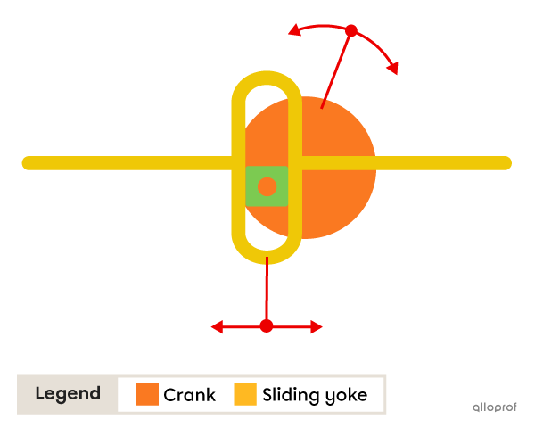
Scotch yoke systems have a sliding yoke, which is different from a connecting rod.
Rotating the crank causes rectilinear translation of the sliding yoke, or vice versa.
This is a reversible system, just like the connecting rod and crank system.
Rack and pinion systems transform rotational motion of the pinion into bidirectional rectilinear translational motion of the rack, and vice versa.

This system contains a wheel gear, or a pinion, and a toothed rod, or a rack. As the pinion rotates, its teeth fit between the rack’s teeth, driving the rack’s rectilinear translation. The opposite is also possible: as the rack moves in rectilinear translation, its teeth fit between the pinion’s teeth, driving the pinion to rotate.
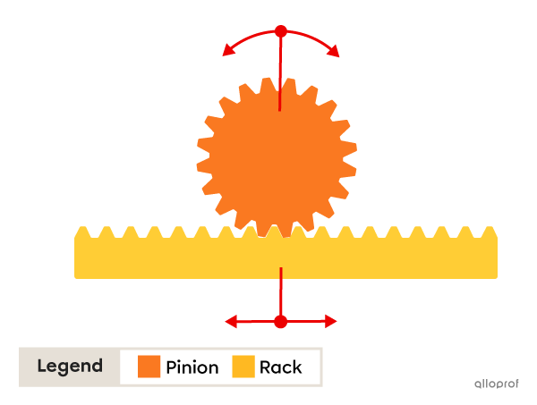
This is a reversible system, because both the pinion and the rack can be either the driver component or driven component.
| Advantages | Disadvantages |
|---|---|
|
|
A car’s steering system relies on a rack and pinion system. The steering wheel is attached to the pinion. Turning the steering wheel causes the pinion to rotate, which drives the translational motion of the rack. When the rack moves, it causes the wheels to move as well.

Worm and rack systems transform the rotational motion of the worm screw into the bidirectional rectilinear translational motion of the rack.

This system is very similar to the rack and pinion. It uses a worm instead of a wheel gear (pinion). As the worm rotates, the rack undergoes rectilinear translation.
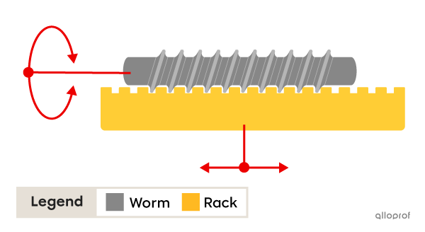
This is an irreversible system, because only the worm can activate it. The translation of the rack cannot drive the worm to rotate. In this system, the rotating worm is always the driver component and the translating rack is always the driven component.
| Advantages | Disadvantages |
|---|---|
|
|
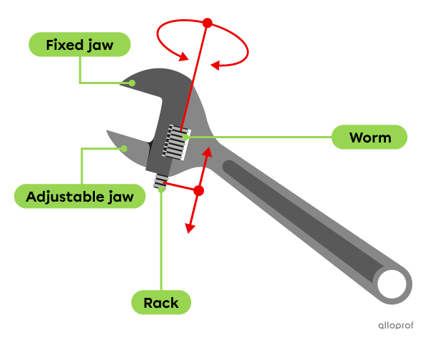
An adjustable wrench also uses a worm-rack system. When the worm screw is rotated, the rack undergoes rectilinear translation. The adjustable jaw can then move to make the space between the two jaws bigger or smaller.
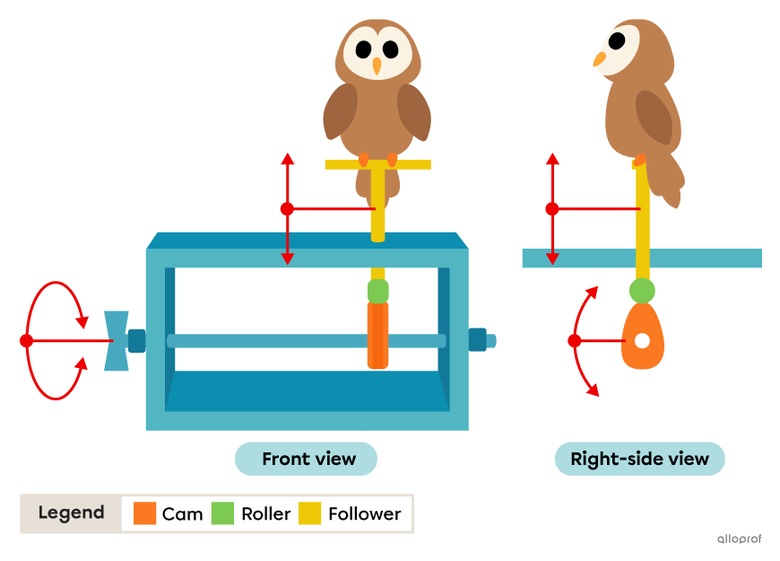
Cam and roller systems, sometimes called cam and follower systems, transform the cam’s rotational motion into bidirectional rectilinear translation of the roller and/or follower.

The cam is the part of the system that is usually shaped like an egg. It may also be a disc with an irregular shape. Its purpose is to push and drive the motion of a roller or follower. Cams come in different shapes (circular, oval, curved, etc.).
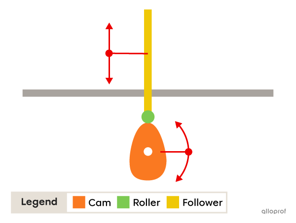
As the cam rotates, the roller or follower moves up and down (reciprocating motion), undergoing rectilinear translation.
The cam’s rotational axis may be off-centre. Cams designed this way are called eccentric.
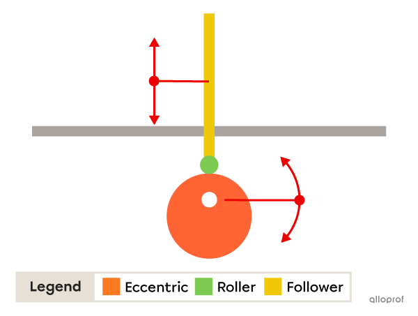
This system is irreversible, because only the cam can activate it. Rectilinear translation of the roller does not set the cam in motion. The rotating cam is always the driver component that drives the rectilinear translation of the roller, the driven component.
| Advantages | Disadvantages |
|---|---|
|
|
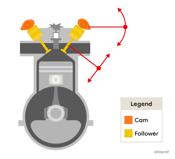
There are cam and follower systems in combustion engines. Initially, when the cam pushes against the follower, gas can enter the combustion chamber. Once the gas is compressed and the combustion (energy production) occurs, the gas can escape out the opposite side: another cam pushes on the follower, opening the exhaust pipe.
In this toy, rotating the handle causes the cam to rotate. When the longest part of the cam reaches the top of its rotation, the owl attached to the follower moves straight up (rectilinear translation). On the other hand, when the longest part of the cam is below the rotational axis, the owl moves straight down (rectilinear translation). The end result is an owl that goes straight up and down via reciprocating bidirectional translation.
