A motion transmission system transmits motion between two components without changing the type of motion. However, the rotational speed of the part initiating motion (driver component) may be different from the rotational speed of the part receiving the motion (driven component).
A speed change is a variation between the rotational speed of the driver component and the rotational speed of the driven component.
The speed change can be determined based on the motion transmission system or the torque involved.
It is possible to determine whether the system is increasing or decreasing the rotational speed by analyzing the size or number of teeth on the driver and driven components.
The following table shows how to determine the speed change in systems with wheel gears and in systems with friction gears or pulleys.
| Gear trains and sprocket systems | Friction gear and pulley systems |
|---|---|
| To determine the speed change in these systems, the number of teeth on each wheel gear is used. The teeth on the gears found within the same system must be identical in size and shape. Therefore, a wheel with more teeth always has a larger diameter. | To determine the speed change in these systems, the diameter of each friction gear or pulley must be used. |
When the driver gear has more teeth than the driven gear, there is an increase in the rotational speed of the driven gear. |
When the driver gear has a larger diameter than the driven gear, there is an increase in the rotational speed of the driven gear. |
When the driver gear has fewer teeth than the driven gear, there is a decrease in the rotational speed of the driven gear. |
When the driver gear has a smaller diameter than the driven gear, there is an decrease in the rotational speed of the driven gear. |
When the driver gear has the same number of teeth as the driven gear, the rotational speed does not change. |
When the driver gear has the same diameter as the driven gear, the rotational speed does not change. |
Note: In this table and throughout this section of the concept sheet, the driver component in each system is on the left (green) and the driven component is on the right (blue).
In a motion transmission system with two gears of different sizes, the smaller gear always rotates faster, and the larger gear always rotates slower.
-
If the motion is transmitted from a small gear to a large gear, the speed decreases.
-
If the motion is transmitted from a large gear to a small gear, the speed increases.
-
In this gear train, the driver wheel gear has 24 teeth, while the driven wheel gear has 16. Since the driven wheel gear has fewer teeth, it rotates faster than the driver wheel gear. This results in a speed increase.

-
In this friction gear system, the driver gear has a diameter of |\text{3 cm},| while the driven gear has a diameter of |\text{6 cm}.| Since the driven gear has a larger diameter, it rotates slower than the driver gear. This results in a speed decrease.

-
In this friction gear system, the driver gear and the driven gear have the same diameter |(\text{4 cm}).| Since they have the same diameter, their rotational speed is the same. There is no speed change.

The rotational speed of the driver and driven gears can be compared using a ratio called a gear ratio in gear trains and sprocket systems or a diameter ratio in friction gear and pulley systems.
||\text{Gear ratio}= \dfrac{\text{Number of teeth on the driver gear}}{\text{Number of teeth on the driven gear}}||
||\text{Diameter ratio}= \dfrac{\text{Driver gear diameter }}{\text{Driven gear diameter}}||
-
A ratio greater than |1| indicates that the driver gear turns slower than the driven gear: there is an increase in speed.
-
A ratio less than |1| indicates that the driver gear turns faster than the driven gear: there is a decrease in speed.
-
A ratio equal to |1| means that the driver and driven gears turn at the same speed: there is no speed change.
-
In this gear train, the driver gear has 24 teeth, while the driven gear has 16.
The gear ratio is calculated as follows.
|\begin{align}\text{Gear ratio} &= \dfrac{\text{Number of teeth on the driver gear}}{\text{Number of teeth on the driven gear}}\\ \text{Gear ratio}&= \dfrac{\text{24 teeth}}{\text{16 teeth}}\\ \text{Gear ratio}&=1.5\end{align}|
Since the ratio is greater than |1| |(1.5 > 1),| there is an increase in speed.
It is also true that the driven gear has a rotational speed |1.5| times the rotational speed of the driver gear.

-
In this friction gear system, the driver gear has a diameter of |\text{3 cm},| while the driven gear has a diameter of |\text{6 cm}.|
The diameter ratio is calculated as follows.
|\begin{align}\text{Diameter ratio}&= \dfrac{\text{Driver gear diameter }}{\text{Driven gear diameter}} \\ \text{Diameter ratio}&= \dfrac{\text{3 cm}}{\text{6 cm}}\\ \text{Diameter ratio}&=0.5\end{align}|
Since the ratio is less than |1| |(0.5 < 1),| there is a decrease in speed.
We can also say that the speed of the driven gear is |0.5| times the speed of the driver gear.

-
In this friction gear system, the driver gear and the driven gear have the same diameter |(\text{4 cm}).|
The diameter ratio is calculated as follows.
|\begin{align}\text{Diameter ratio}&= \dfrac{\text{Driver gear diameter}}{\text{ Driven gear diameter}}\\ \text{Diameter ratio}&= \dfrac{\text{4 cm}}{\text{4 cm}}\\ \text{Diameter ratio}&=1\end{align}|
Since the ratio is equal to |1,| there is no change in speed.

The speed ratio allows a quantitative comparison of the speeds of the driver and driven gears.
The speed ratio value is equivalent to the gear ratio or diameter ratio value.
||\text{Speed ratio }=\dfrac{\text{Driven gear speed}}{\text{Driver gear speed}}||
||\text{Speed ratio }=\text{Gear or diameter ratio}||
These formulas are used to calculate the speeds of the driven or driver gears. By isolating these variables in the ratio formulas, the following formulas are obtained.
||\text{Driven gear speed} = {\text{Speed ratio}}\times {\text{Driver gear speed}}||
||\text{Driver gear speed}=\dfrac{\text{Driven gear speed}}{\text{Speed ratio}}||
What is the driven gear speed in the following system, if the green gear is the driver gear and it rotates at a speed of 10 revolutions per minute (RPM)?

To calculate the driven gear speed, first, the gear ratio between the two wheel gears must be determined.
|\begin{align}\text{Gear ratio} &= \dfrac{{\color{green}{\text{Number of teeth on the driver gear}}}}{{\color{blue}{\text{Number of teeth on the driven gear}}}}\\ \text{Gear ratio} &= \dfrac {\color{green} {15}}{\color{blue} {10}}\\ \text{Gear ratio} &= 1.5 \end{align}|
The driven gear speed is then calculated with the corresponding formula. The gear ratio is equivalent to the speed ratio, so it can be replaced in the equation to find the value of the driven gear speed.
|\begin{align}\text{Driven gear speed}&= \text{Gear ratio}\times \text{Driver gear speed}\\\\ \text{Gear ratio}&=\text{Speed ratio}\\\\ \text{Driven gear speed} &= {\text{Speed ratio}}\times {\text{Driver gear speed}}\\ \text{Driven gear speed} &= 1{.}5 \times {\text{10 rpm}}\\ \text{Driven gear speed} &= {\text{15 rpm}} \end{align}|
The speed of the driven gear is 15 RPM.
The worm and worm gear system is irreversible: the worm is always the driver component, and it transmits rotational motion to the worm gear, the driven component. This system is mainly used in cases where the rotational speed must be greatly reduced during the transmission of rotation. For each full rotation of the worm, the worm gear only rotates by the distance equivalent to one tooth. The more teeth there are on the worm gear, the slower its speed.
The worm must complete one rotation for the worm gear to move by one tooth.
Since the worm gear has 16 teeth, the worm must rotate 16 times in order for the worm gear to complete one full rotation.
The worm turns faster than the worm gear, so there is a decrease in speed.
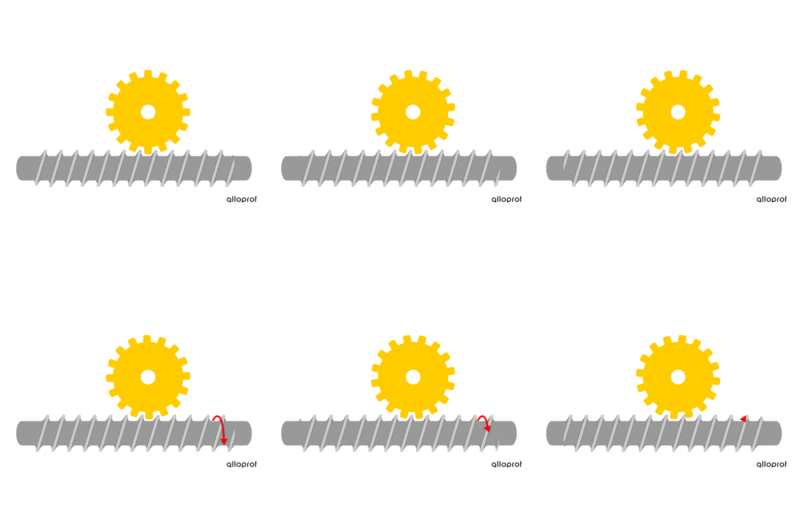
This decrease in speed can be quantified by calculating the following speed ratio.
|\text{Speed ratio}= \dfrac{\text{1}}{\text{Number of teeth on the worm gear}}|
The ratio is always less than |1,| meaning that the worm always rotates faster than the worm gear: there is always a decrease in speed.
This worm and worm gear system has a worm gear with 16 teeth. What is its speed ratio?
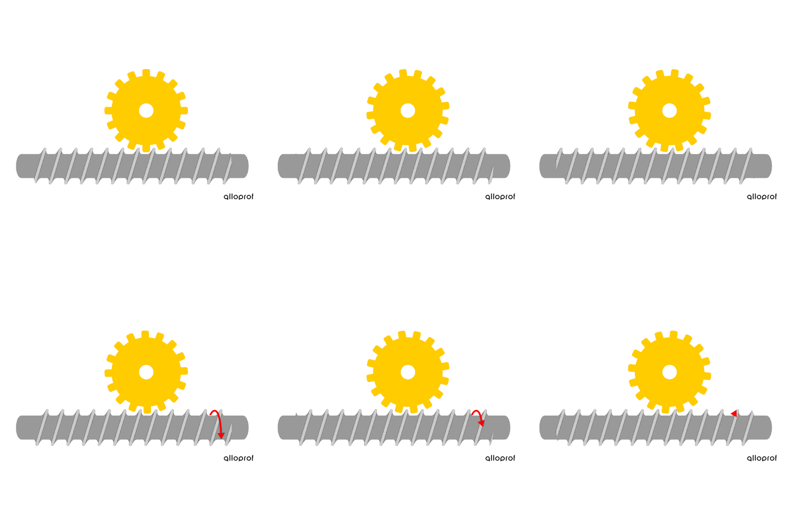
The speed ratio can be calculated as follows.
|\begin{align}\text{Speed ratio}&= \dfrac{\text{1}}{\text{Number of teeth on the worm gear}}\\ \text{Speed ratio}&= \dfrac{\text{1}}{\text{16}}\\ \text{Speed ratio}&= 0.0625\end{align}|
This means that for one full rotation of the worm, the worm gear makes 0.0625 rotations, or 1/16 of a rotation. The wheel gear rotates 16 times slower than the worm. The worm must rotate 16 times before the wheel gear makes one complete rotation.
Torque is the combination of two forces of the same magnitude, but applied in opposite directions, which produces or prevents a rotational motion around an axis.
For two forces of equal magnitude and opposite directions to produce or prevent rotational motion, their points of application on a part must be misaligned.
Two people facing each other are pushing on a piece of furniture with the same force. Since they are perfectly aligned, the applied forces have no effect on the motion of the object. Instead, it will be compressed. These forces do not generate torque.
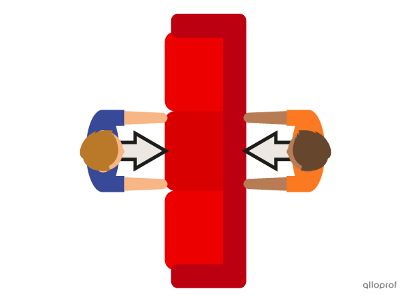
If the points of application of the two forces are misaligned, rotation can occur. When the two people move further away from each other and apply sufficient force, they can cause the furniture to rotate. The combination of forces applied by the two people produces torque.

Torque is required for some technological objects to operate.
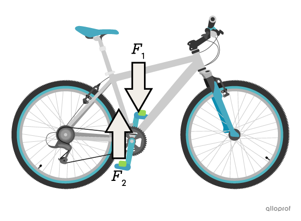
The pedal mounts on some bicycles allow cyclists to secure their feet to the pedals. They can then use one foot to push one pedal down |(F_1),| while the other foot pulls the other pedal up |(F_2).| The forces on each pedal are misaligned and in opposite directions. They form a force couple that generates torque, causing the crankset to rotate around its axis.
There are two types of torque: driving torque and resisting torque.
-
Driving torque, also called engine torque, produces motion or increases the rotational speed of a system.
-
Resisting torque prevents motion or slows the rotational speed of a system.
Driving torque and resisting torque can be applied simultaneously to the same system. If the driving torque is greater than the resisting torque, the rotational speed of the system increases. On the other hand, if the resisting torque is greater than the driving torque, the rotational speed of the system decreases.
When a cyclist goes up a hill on a bicycle, the forces applied to the pedals cause the wheel to rotate. These forces generate driving torque. At the same time, the force of gravity opposes the cyclist’s ascent and generates resisting torque on the crankset.
If the driving torque applied by the cyclist is greater than the resisting torque generated by gravity, the crankset rotates faster: the cyclist accelerates.
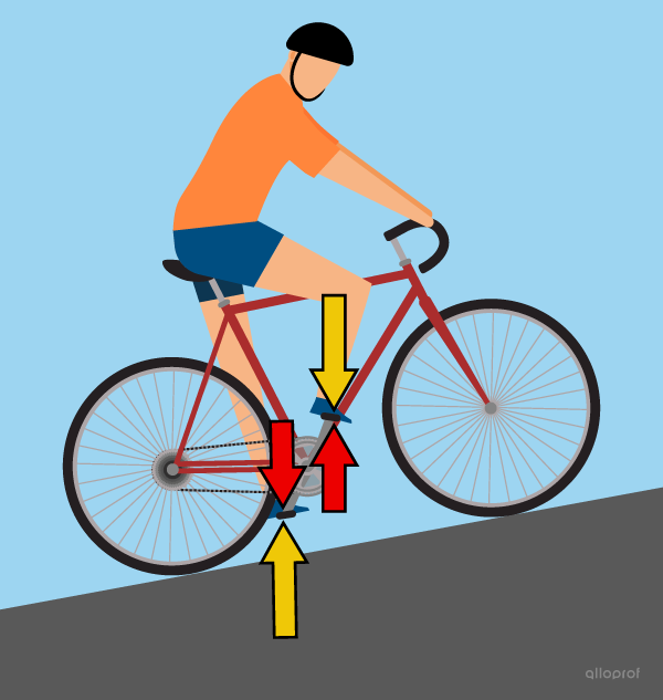
If the hill is too steep and the resisting torque generated by gravity is greater than the driving torque applied by the cyclist, the crankset rotates slower: the cyclist slows down.
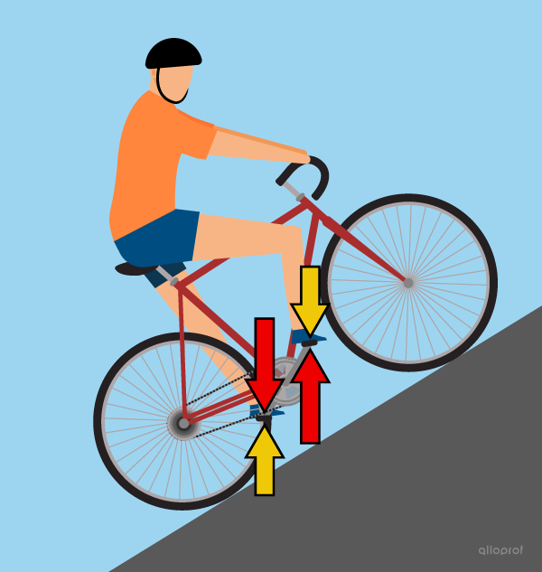
Speed changes caused by differences in the intensity of driving and resisting torque are summarized in the following table.
| Comparison of torques | Effect on component’s speed |
|---|---|
| Driving torque = Resisting torque | No speed change |
| Driving torque > Resisting torque | Increase in speed |
| Driving torque < Resisting torque | Decrease in speed |