Choose your level:
A switch is an electrical device with a movable conductive part. The position of this movable part determines whether the circuit is open or closed.
In an electrical circuit, a switch is responsible for the control function.
The following switches are studied in Applied Science and Technology (AST) in Secondary 3:
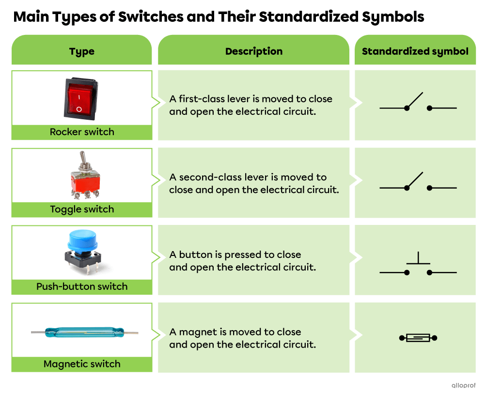
Sources: Adapted from blacklionder, Shutterstock.com, AYL Wikimedia Commons.com, ra3rn, Shutterstock.com, Darkdiamond67, Shutterstock.com, and CobraCZ, Shutterstock.com.
It is sometimes difficult to tell the difference between a rocker switch and a toggle switch, since they both contain a lever.
The main differences are the location of the lever pivot and where the force must be applied to make the switch move.
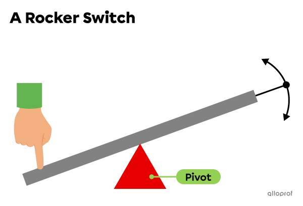
The pivot of a rocker switch is located between the two ends of the lever. Either end is pressed to close and open the switch.
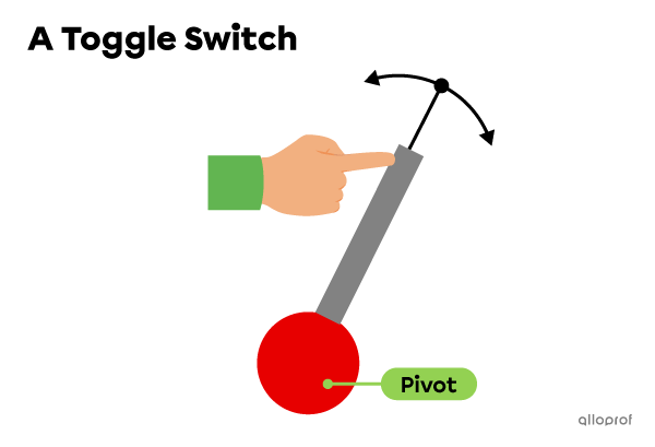
The pivot of a toggle switch is located at one end of the lever. Only one end is pressed to close and open the switch.
To control an electrical circuit with a rocker switch, it is opened and closed by tilting one end or the other of a first-class lever.
One end of the lever closes the circuit and allows current to flow. Once tilted, it remains in its position and maintains contact between the conductive parts.
The other end of the lever opens the circuit and prevents current flow. Once toggled, it remains in its position and there is no contact between the conductive parts.
The switch is rocked back and forth, hence its name.
Here are several examples of rocker switches.
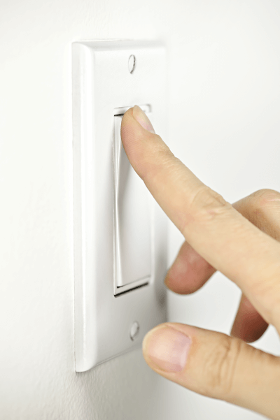
Source: Elena Elisseeva, Shutterstock.com

Source: Mariana_Rusanovschi, Shutterstock.com
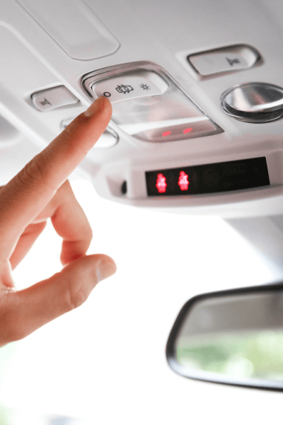
Source: RaspberryStudio, Shutterstock.com
To control an electrical circuit with a toggle switch, it is opened and closed by moving one end of a second-class lever.
One position of the lever allows the conducting parts to make contact. The circuit closes and current flows.
The other position of the lever prevents contact between the conducting parts. The circuit opens and the current stops flowing.
The switch is toggled back and forth, hence its name.
Here are several examples of toggle switches.
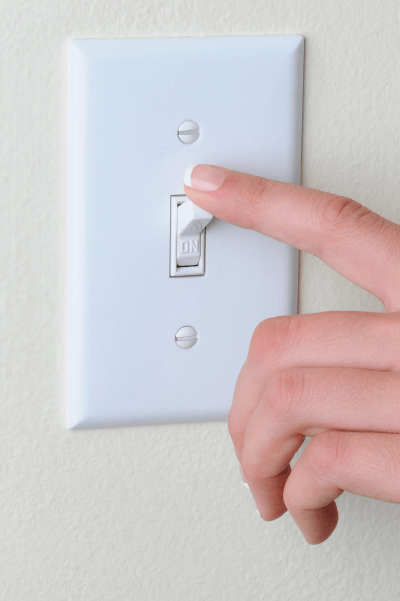
Source: Steve Cukrov, Shutterstock.com
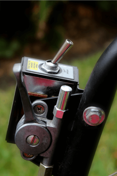
Source: GSPhotography, Shutterstock.com
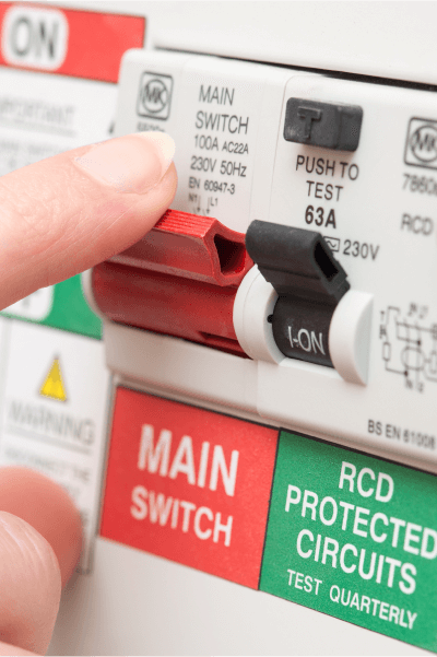
Source: photographyfirm, Shutterstock.com
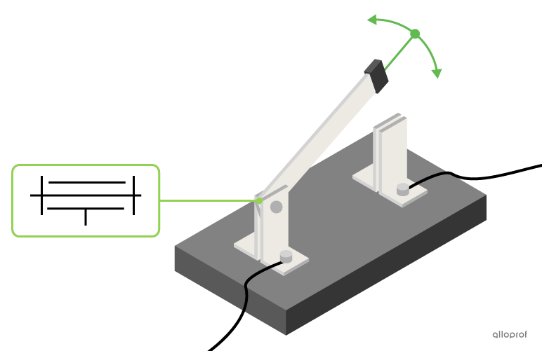
A blade switch, sometimes called a knife switch, is also an example of a toggle switch. In this device, a flat metal bar is placed between two supports, also made of metal.
One end of the bar is partially linked to one of the supports, which enables rotational guiding control. The other end of the bar is free.
To close the switch, the bar is lowered until its free end touches the second support. To open the switch, the bar is lifted so that it is no longer in contact with the second support.
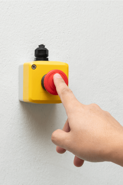
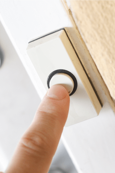
To control an electrical circuit with a push-button switch, it is opened and closed by pressing or releasing a button.
When the button is pushed, the movable part of the switch comes into contact with two other conductive parts. The circuit closes and the current flows. Sometimes the button has to be pressed and held down to keep the circuit closed.
When the button is released, a spring forces the movable part of the switch back up. There is no longer any contact between the conducting parts. The circuit opens and the current stops flowing.
Here are several examples of push-button switches.
Source: Wongsakorn Napaeng, Shutterstock.com

Source: Me dia, Shutterstock.com
Source: Happy Stock Photo, Shutterstock.com
To control an electrical circuit with a magnetic switch, it is opened and closed by using a magnetic field.
Generally, the magnetic field required to control the switch is produced by a magnet placed nearby. The position of the magnet relative to the switch closes or opens the circuit.
When the magnet is brought close to the magnetic switch, the conducting parts are attracted to each other and come into contact. The circuit closes and the current flows.
When the magnet is moved away from the magnetic switch, the conductive parts are no longer attracted to each other and their contact is broken. The circuit opens and the current stops flowing.
A magnetic switch can also work in reverse, which means that when the magnet is brought closer, the conductive parts repel each other and the circuit opens. When the magnet is moved away, the conductive parts make contact again and the circuit closes.
In short, the operation of the magnetic switch depends on whether the magnetic field of the magnet causes attraction or repulsion between the conductive parts of the switch.
Here are several examples of magnetic switches.
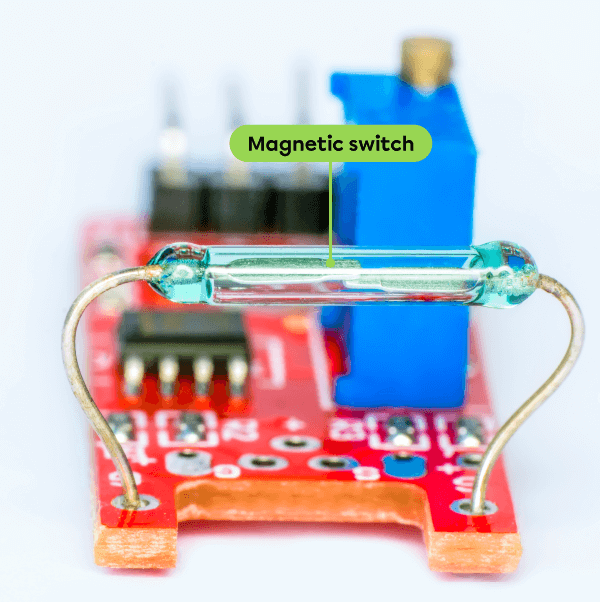
Source: Adapted from Darkdiamond67, Shutterstock.com
This electronic circuit is controlled by a magnetic switch. Moving a magnet closer to or further away from the switch is all it takes to close or open the circuit.
Source: Adapted from AndreyKac, Shutterstock.com
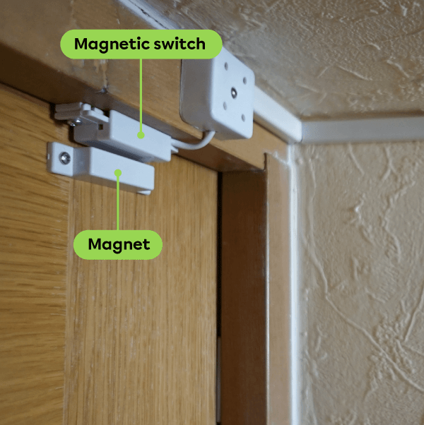
An alarm system generally includes a magnetic switch installed on a door frame. A magnet mounted on the door controls the switch.
Source: Adapted from Jo Panuwat D, Shutterstock.com
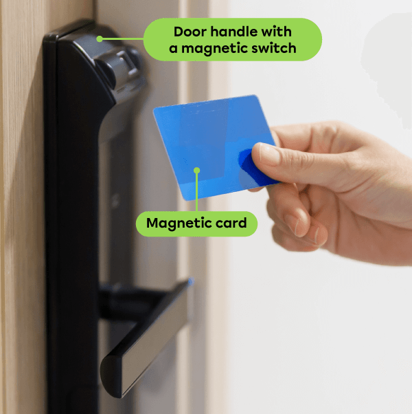
A hotel room door handle usually includes a magnetic switch that is controlled by a magnetic card.
A switch is an electrical device with a movable conductive part. The position of this movable part determines whether the circuit is open or closed.
In an electrical circuit, a switch is responsible for the control function.
The following switches are studied in Secondary 4:
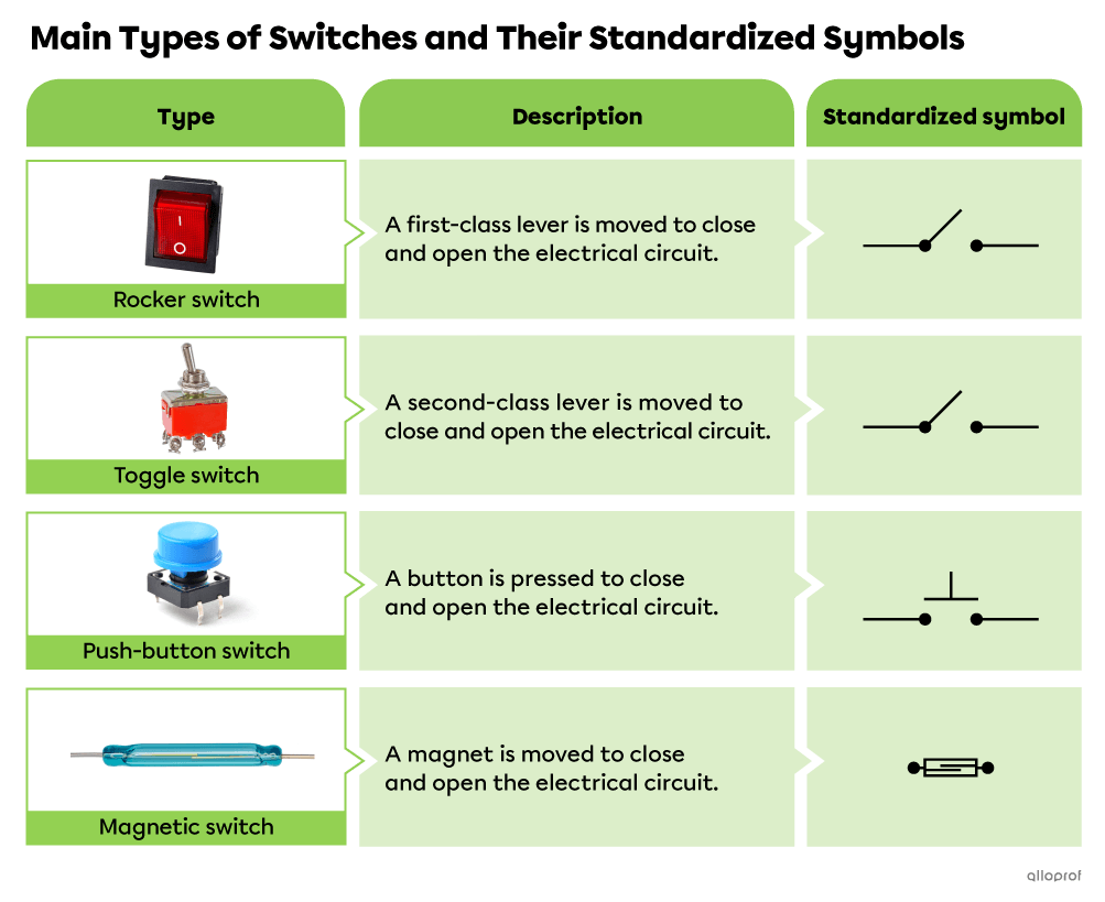
Source: Adapted from blacklionder, Shutterstock.com, AYL Wikimedia Commons.com, ra3rn, Shutterstock.com, Darkdiamond67, Shutterstock.com, and CobraCZ, Shutterstock.com.
It is sometimes difficult to tell the difference between a rocker switch and a toggle switch, since they both contain a lever.
The main differences are the location of the lever pivot and where the force must be applied to make the switch move.
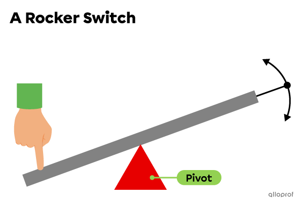
The pivot of a rocker switch is located between the two ends of the lever. Either end is pressed to close and open the switch.
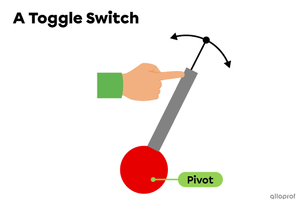
The pivot of a toggle switch is located at one end of the lever. Only one end is pressed to close and open the switch.
To control an electrical circuit with a rocker switch, it is opened and closed by tilting one end or the other of a first-class lever.
One end of the lever closes the circuit and allows current to flow. Once tilted, it remains in its position and maintains contact between the conductive parts.
The other end of the lever opens the circuit and prevents current flow. Once toggled, it remains in its position and there is no contact between the conductive parts.
The switch is rocked back and forth, hence its name.
Here are several examples of rocker switches.
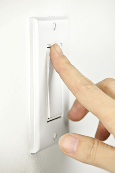
Source: Elena Elisseeva, Shutterstock.com
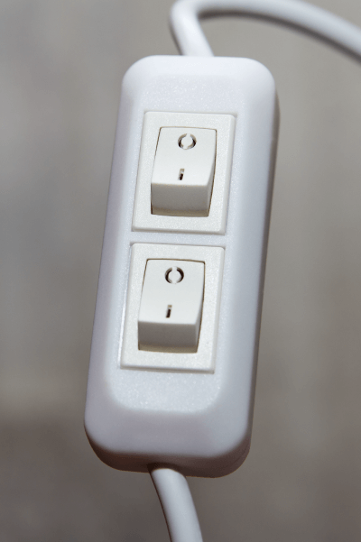
Source: Mariana_Rusanovschi, Shutterstock.com
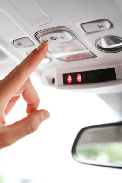
Source: RaspberryStudio, Shutterstock.com
To control an electrical circuit with a toggle switch, it is opened and closed by moving one end of a second-class lever.
One position of the lever allows the conducting parts to make contact. The circuit closes and current flows.
The other position of the lever prevents contact between the conducting parts. The circuit opens and the current stops flowing.
The switch is toggled back and forth, hence its name.
Here are several examples of toggle switches.
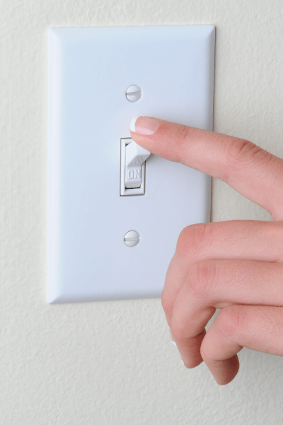
Source: Steve Cukrov, Shutterstock.com
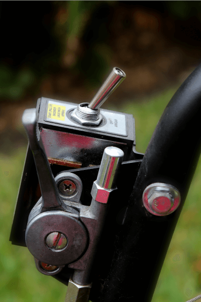
Source: GSPhotography, Shutterstock.com
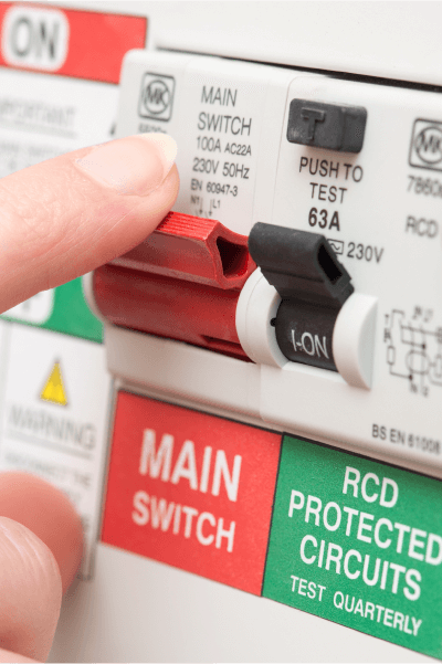
Source: photographyfirm, Shutterstock.com
A blade switch, sometimes called a knife switch, is also an example of a toggle switch. In this device, a flat metal bar is placed between two supports, also made of metal.
One end of the bar is partially linked to one of the supports, which enables rotational guiding control. The other end of the bar is free.
To close the switch, the bar is lowered until its free end touches the second support. To open the switch, the bar is lifted so that it is no longer in contact with the second support.

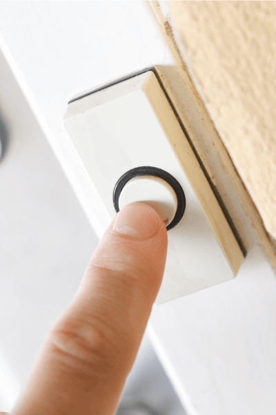
To control an electrical circuit with a push-button switch, it is opened and closed by pressing or releasing a button.
When the button is pushed, the movable part of the switch comes into contact with two other conductive parts. The circuit closes and the current flows. Sometimes the button has to be pressed and held down to keep the circuit closed.
When the button is released, a spring forces the movable part of the switch back up. There is no longer any contact between the conducting parts. The circuit opens and the current stops flowing.
Here are several examples of push-button switches.
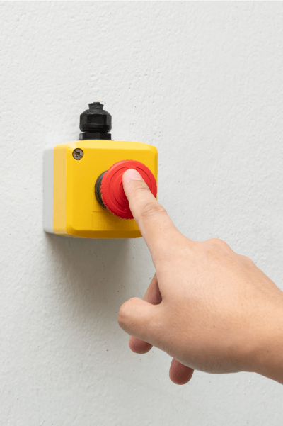
Source: Wongsakorn Napaeng, Shutterstock.com

Source: Me dia, Shutterstock.com
Source: Happy Stock Photo, Shutterstock.com
To control an electrical circuit with a magnetic switch, it is opened and closed by using a magnetic field.
Generally, the magnetic field required to control the switch is produced by a magnet placed nearby. The position of the magnet relative to the switch closes or opens the circuit.
When the magnet is brought close to the magnetic switch, the conducting parts are attracted to each other and come into contact. The circuit closes and the current flows.
When the magnet is moved away from the magnetic switch, the conductive parts are no longer attracted to each other and their contact is broken. The circuit opens and the current stops flowing.
A magnetic switch can also work in reverse, which means that when the magnet is brought closer, the conductive parts repel each other and the circuit opens. When the magnet is moved away, the conductive parts make contact again and the circuit closes.
In short, the operation of the magnetic switch depends on whether the magnetic field of the magnet causes attraction or repulsion between the conductive parts of the switch.
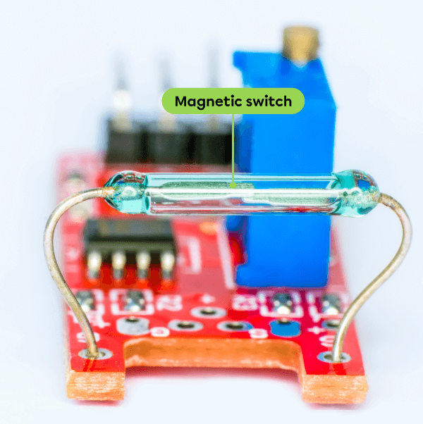
Here are several examples of magnetic switches.
Source: Adapted from Darkdiamond67, Shutterstock.com
This electronic circuit is controlled by a magnetic switch. Moving a magnet closer to or further away from the switch is all it takes to close or open the circuit.
Source: Adapted from AndreyKac, Shutterstock.com
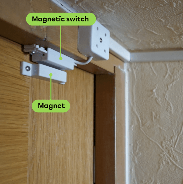
An alarm system generally includes a magnetic switch installed on a door frame. A magnet mounted on the door controls the switch.
Source: Adapted from Jo Panuwat D, Shutterstock.com
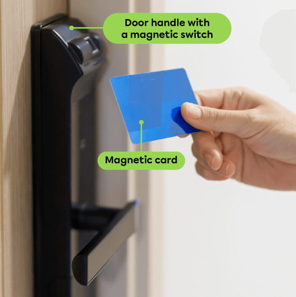
A hotel room door handle usually includes a magnetic switch that is controlled by a magnetic card.
A switch can be described using the number of poles, which is the number of contacts that can be used to close it.
-
A single-pole or unipolar switch has 1 pole. It has only 1 contact that closes the switch at one contact point at a time.
-
A double-pole or bipolar switch has 2 poles. It has only 2 contacts that close the switch at 2 contact points at a time.
A switch can also be described in terms of the number of throws, which is the number of closed positions that allow the current to flow.
-
A single-throw or unidirectional switch has 1 throw. It has only 1 closed position that allows the current to flow along 1 path.
-
A double-throw or bidirectional switch has 2 throws. It has 2 closed positions that allow the current to flow along 2 paths.
By combining the number of possible poles and throws, 4 different switches are possible.
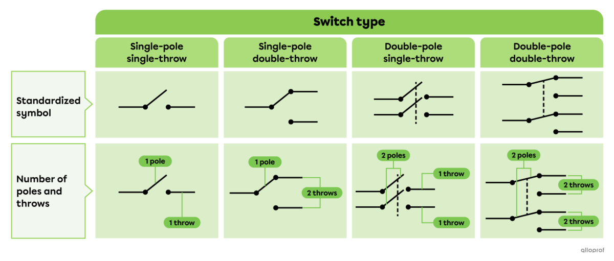
Single-Pole Single-Throw Switches
A single-pole single-throw switch, also called a unipolar unidirectional switch, has 1 pole and 1 throw. This means that the switch makes only one contact at a time and there is only one position that allows current to flow along one path.
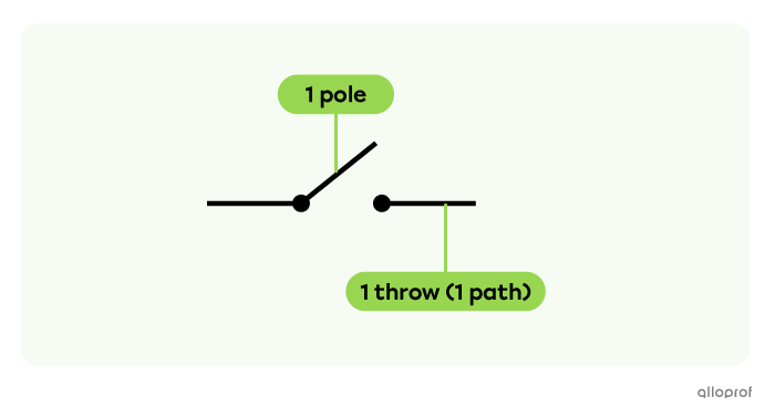
This electrical diagram shows a light bulb controlled by a single-pole single-throw switch.

The switch is open. The pole is not in the only possible closed position. No current is flowing and the bulb is off.

The switch is closed. The pole is in the only possible closed position. Current is flowing and the bulb is on.
Single-Pole Double-Throw Switches
A single-pole double-throw switch, also called a unipolar bidirectional switch, has 1 pole and 2 throws. This means that the switch makes only one contact at a time and there are two positions that allow current to flow along two different paths.
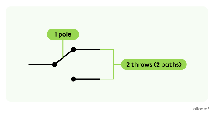
This electrical diagram shows two light bulbs controlled by a single-pole double-throw switch.
This switch can be used to turn on either bulb, but not both at the same time.
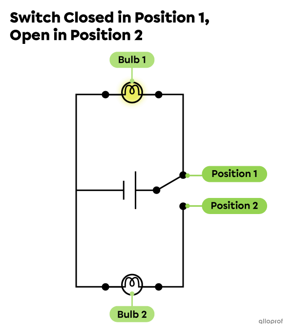
The switch is closed in Position 1 and open in Position 2. The current is flowing through Bulb 1 but not through Bulb 2. Bulb 1 is on and Bulb 2 is off.
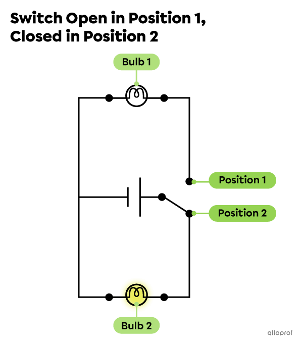
The switch is closed in Position 2 and open in Position 1. The current is flowing through Bulb 2 but not through Bulb 1. Bulb 2 is on and Bulb 1 is off.
Double-Pole Single-Throw Switches
A double-pole single-throw switch, also called a bipolar unidirectional switch, has 2 poles and 1 throw per pole. This means that the switch makes two contacts at a time and there is only one position that allows current to flow along one path per pole.
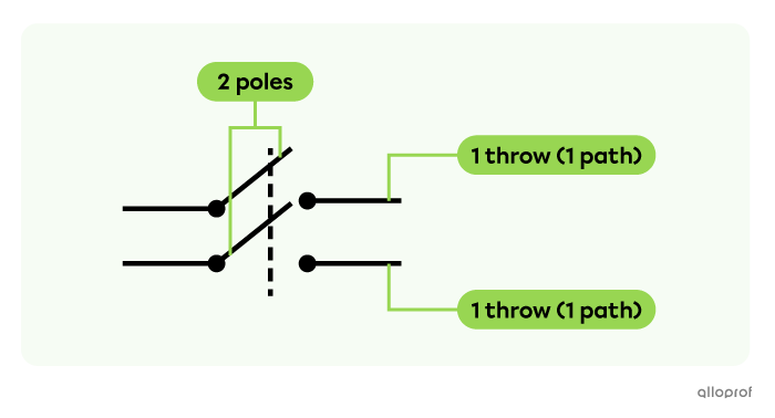
This electrical diagram shows two light bulbs controlled by a double-pole single-throw switch.
This switch can be used to turn on both bulbs or turn off both bulbs.

The switch is open. The two poles are not in the only possible closed position. No current is flowing in either of the two bulbs and they are both off.
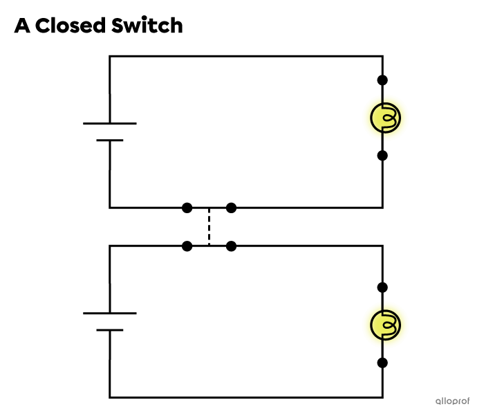
The switch is closed. The two poles are in the only possible closed position. Current is flowing in both bulbs and they are both on.
Double-Pole Double-Throw Switches
A double-pole double-throw switch, also called a bipolar bidirectional switch, has 2 poles and 2 throws per pole. This means that the switch makes two contacts at a time and there are two possible positions that allow current to flow along two paths per pole.
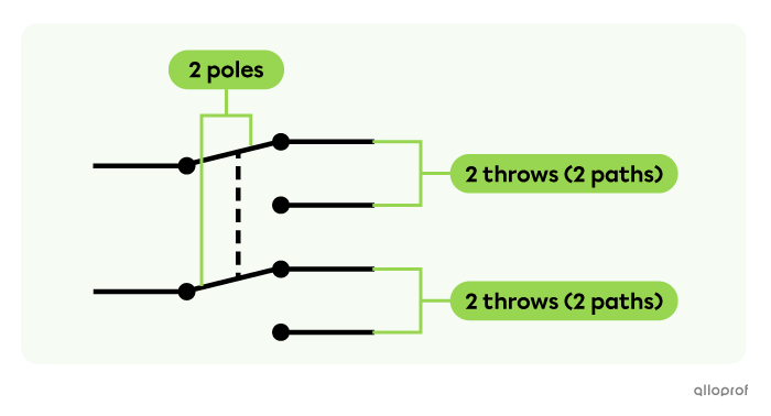
This electrical diagram shows four light bulbs controlled by a double-pole double-throw switch.
This switch can be used to turn on two out of four light bulbs at a time, but not to turn on all four at once.
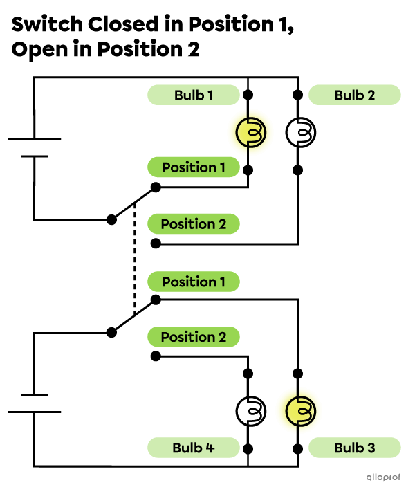
The switch is closed in Position 1 and open in Position 2. The current is flowing through bulbs 1 and 3 but not through bulbs 2 and 4. Bulbs 1 and 3 are on, bulbs 2 and 4 are off.
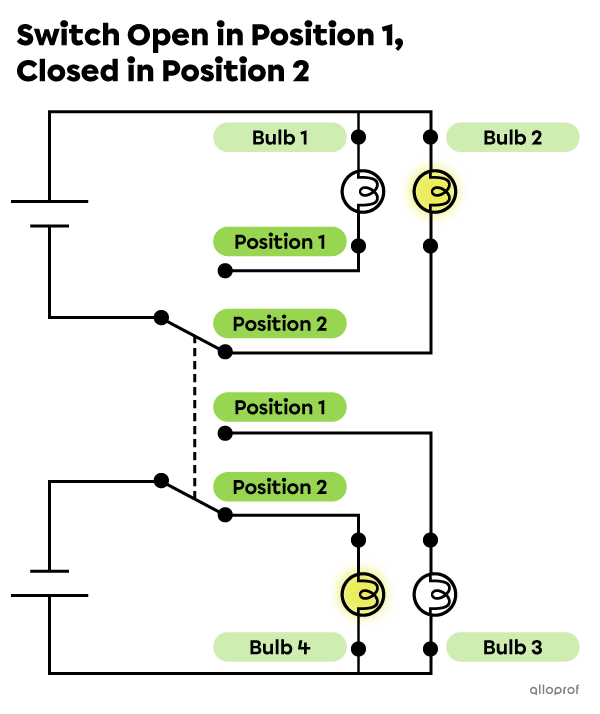
The switch is closed in Position 2 and open in Position 1. The current is flowing through bulbs 2 and 4 but not through bulbs 1 and 3. Bulbs 2 and 4 are on, bulbs 1 and 3 are off.