An electrical circuit is a combination of electrical components that are connected to form a closed path through which electric current can flow.
An electrical circuit always includes the following components:
-
A power supply that is a source of the electric current (e.g., a battery).
-
One or more electrical components that transform electrical energy (e.g., a light bulb).
-
Conductive wires that connect the electrical components.
In high school, two types of circuits are explained: series circuit and parallel circuit.
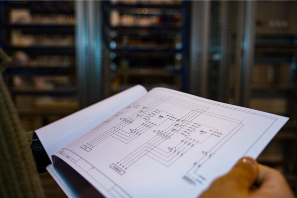
When designing, manufacturing or repairing an electrical circuit, an electrical diagram is generally used as a reference tool. It is a drawing in which the electrical components are represented by standardized symbols.
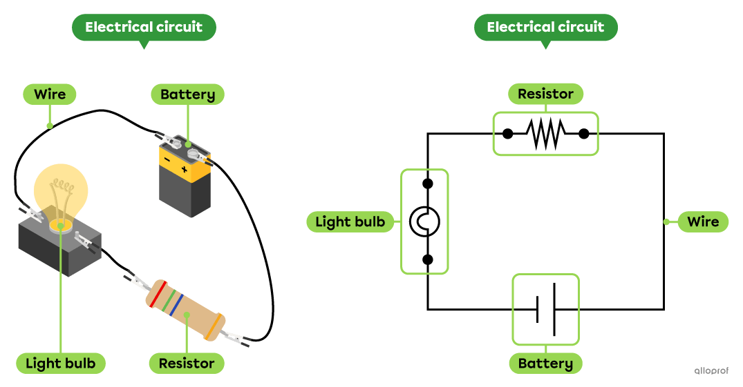
A series circuit is an electrical circuit where the components are connected one after the other to form a single loop to allow the current to flow.
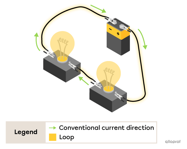
The characteristics of a series circuit
-
The current can only follow one path.
-
The current intensity is the same in all the components of the circuit.
-
When one component of the circuit is faulty, the current stops flowing throughout the circuit.
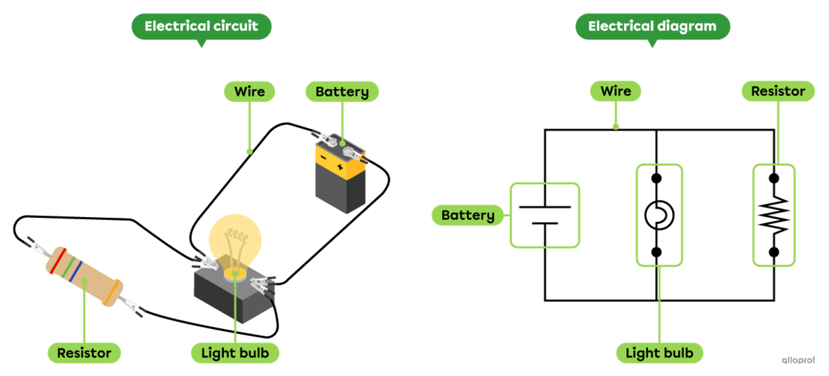
A parallel circuit is an electrical circuit in which the components are connected to form several loops to allow the current to flow.
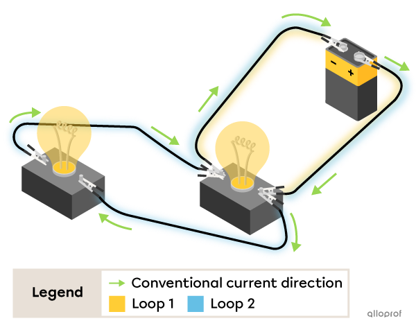
The characteristics of a parallel circuit
-
The current can take several paths.
-
The potential difference across each component of the circuit is the same as that across the current source.
-
When one component of the circuit is faulty, the current continues to flow through the loops that are intact.
Here's an electrical circuit with 2 light bulbs connected in series with a battery. The electric current flows through a single loop.
Both light bulbs are lit.
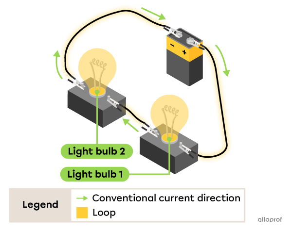
When one of the wires is disconnected, both light bulbs turn off.
This is because the only loop where current could flow is now open and there is no longer any current flowing in this circuit.
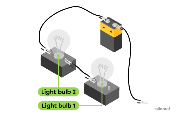
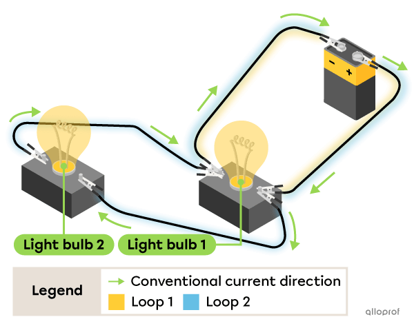
Here's an electrical circuit with two light bulbs connected in parallel with a battery. The electric current flows through two loops.
Both light bulbs are lit.
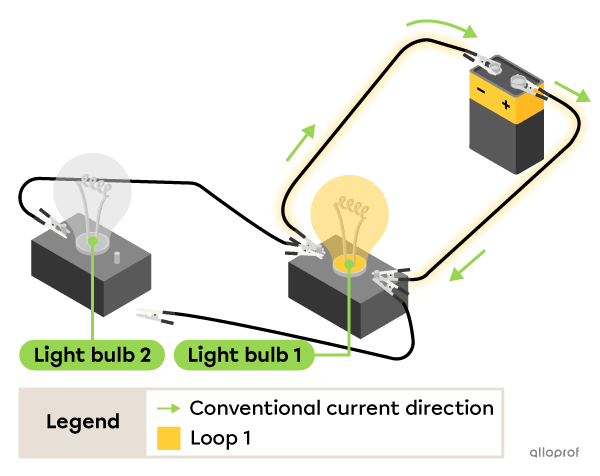
When one of the wires is disconnected from Bulb 2, it turns off but Bulb 1 is still lit.
This is because the loop that allows the current to flow through Bulb 1 is still intact.
À 1 min 27 s, Marie-Ève branche un fil noir dans la borne positive. Par convention, on branche habituellement un fil rouge dans la borne positive, qui est rouge.
À 1 min 48 s, Marie-Ève branche un fil rouge dans la borne négative. Par convention, on branche habituellement un fil noir dans la borne négative, qui est noire.
À 2 min 29 s, Attention! L'intensité du courant et l'intensité lumineuse sont deux concepts différents. Ici, on devrait plutôt dire que « l'intensité lumineuse de deux ampoules semblables est la même » ou encore que « l'intensité du courant circulant à travers des ampoules semblables est la même ».
An electrical diagram is the representation of an electrical circuit using standardized symbols.
An electrical diagram is a drawing of an electrical circuit. Among other things, it describes how the electrical components of the circuit are connected to each other.
In an electrical diagram, each component of the circuit is represented by a standardized symbol. The use of these symbols enables people referring to the electrical diagram to understand and communicate information in a uniform manner.
Source: Txus Lopez, Shutterstock.com
The following table shows the main electrical symbols used in high school.
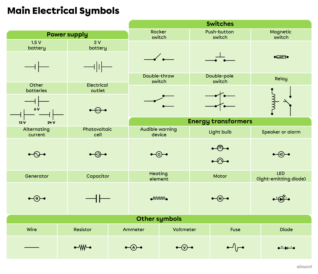
Notes:
-
The double-throw switch, the double-pole switch, the LED, the diode and the capacitor are electrical components seen in Applied Science and Technology (AST) and Environmental Science and Technology (EST).
-
The relay is an electrical component seen in AST only.
Here's a series electrical circuit with its electrical diagram.
Here's a parallel electrical circuit with its electrical diagram.
Pour valider ta compréhension à propos de l'électricité de façon interactive, consulte la MiniRécup suivante :
