A rotation is a geometric transformation that is an isometry.
A rotation, denoted |r_{(\text{centre}, \text{degree})}|, is a geometric transformation that produces an image of an initial figure following a “pivot” which is defined by an angle’s degree and direction, about a point called the centre of rotation.
In a rotation r:
-
the centre of rotation P is a fixed point about which the rotation occurs
-
the angle of rotation, usually represented by a rotation arrow, is a measure in degrees that indicates the rotation value
-
the direction of rotation can be clockwise (in the same direction as the hands of a clock) or counterclockwise (in the opposite direction as the hands of a clock)
The image figure |A’B’C’| is the result of applying a rotation of |72^\circ| to the initial figure |ABC| about point |D.|
It is important to note that particular attention must be paid to the sign that defines the angle of rotation. This means that a positive or negative sign must be associated with clockwise or counter-clockwise rotation.
A clockwise rotation has a negative angle of rotation. A counterclockwise rotation has a positive angle.
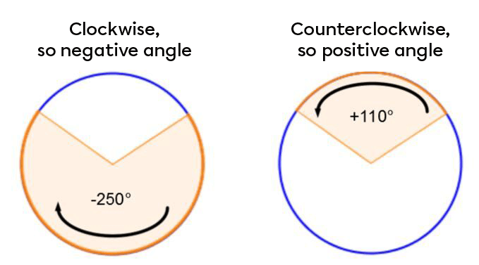
These positive and negative directions are related to the numbering of the quadrants on the Cartesian plane.
All the points on the image figure resulting from a rotation can therefore be associated with their corresponding points on the initial figure. Mathematically speaking, corresponding points have the same position on the initial and image figures.
To distinguish between the corresponding points on the initial figure and the image figure, we use the ‘’ ' ‘’ symbol (called prime). Vertex A in the initial figure becomes vertex A' in the image figure.
The properties of rotations can be used to verify if an image has been generated from a rotation, or to demonstrate the construction of a rotated image.
| Properties of a rotation | Example |
|---|---|
|
The corresponding sides of an initial figure and its image are not necessarily parallel. |
|\overline{AB}\not\parallel\overline{A'B'}|, |\overline{BC}\not\parallel\overline{B'C'}|, |\overline{AC}\not\parallel\overline{A'C'}|  |
|
Rotation conserves orientation, so the order of the corresponding vertices remains the same. |
Vertices |A|, |B| and |C| are placed in 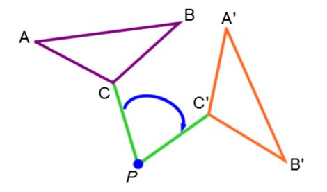 |
|
The line segments drawn to connect corresponding vertices are never parallel. |
|\overline{AA'}\not\parallel\overline{BB'}\not\parallel\overline{CC'}| 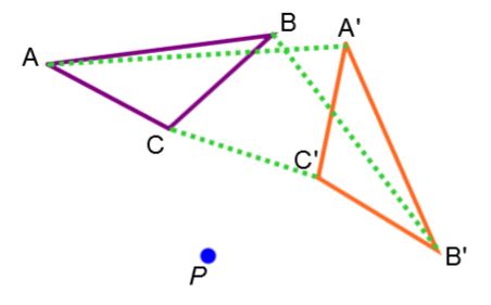 |
There are two ways of constructing an image by rotation:
The image of a rotated figure can be constructed by following these steps:
-
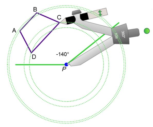
Position the needle point of the compass on the centre of rotation P and draw circles through each vertex of the figure.
-
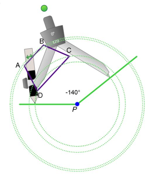
For one vertex of the figure, open the compass to the length of the arc bounded by the angle of rotation and its respective circle.
-
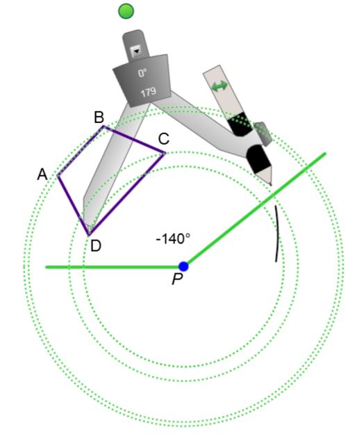
Place the needle point of the compass on the vertex chosen in Step 2 and draw a smaller arc on its respective circle in the direction indicated by the rotation arrow.
-
Repeat steps 2 and 3 for the other vertices of the figure.
-
Use the prime symbol (') to label the image points obtained and then use a ruler to connect the image points in the same way as the initial points.
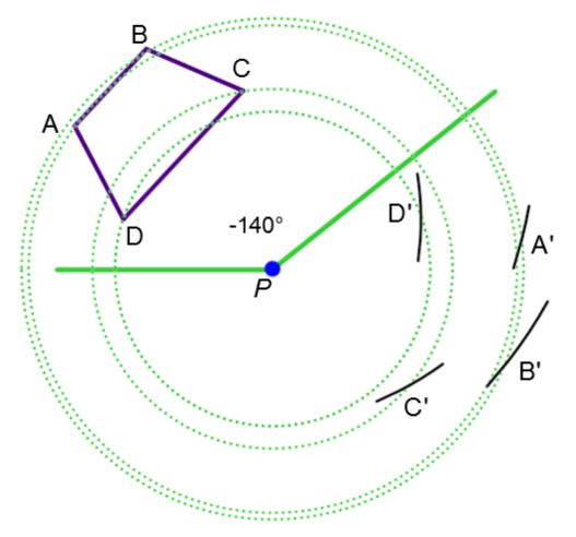
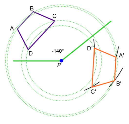
To construct the image of the polygon below using a rotation, follow these steps:
|
1. Position the needle point of the compass on the centre of rotation P and draw circles through each vertex of the figure. |
2. For one vertex of the figure, open the compass to the length of the arc bounded by the angle of rotation and its respective circle. |
|
3. Place the needle point of the compass on the vertex chosen in Step 2 and draw a smaller arc on its respective circle in the direction indicated by the rotation arrow. |
4. Repeat steps 2 and 3 for the other vertices of the figure. |
|
5. Use the prime symbol (') to identify the image points obtained and then use a ruler to connect the image points in the same way as the initial points. |
|
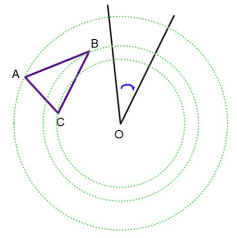
To construct the image of the polygon below using a rotation, follow these steps:
-
For each vertex, make circles centred on O, around which the rotation will occur.
-
Using the protractor, measure the angle of rotation and transfer it by placing the origin of the protractor on the centre of rotation O and the zero aligned with the vertex in question.
-
Repeat Step 2 for the other vertices in the figure to form the image vertices.
-
Identify and connect the image vertices to form the image figure.
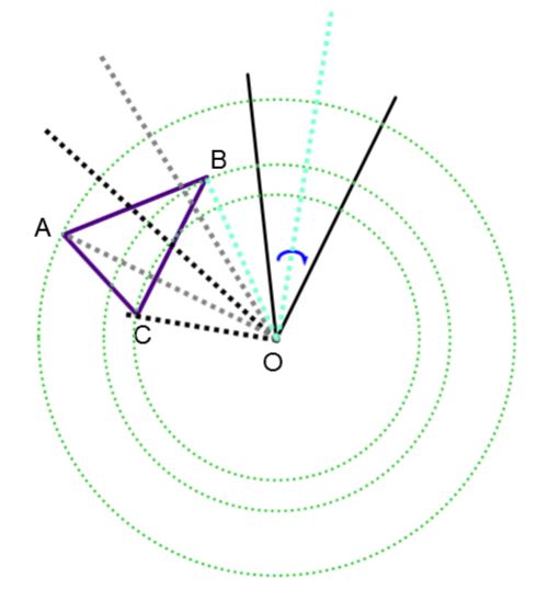
To construct the image of the polygon below using a rotation, follow these steps:
|
1. For each vertex, make circles centred on O, around which the rotation will occur. |
2. Using the protractor, measure the angle of rotation and transfer it by placing the origin of the protractor on the centre of rotation O and the zero aligned with the vertex in question. |
|
3. Repeat Step 2 for the other vertices in the shape to form the image vertices. |
4. Identify and connect the image vertices to form the image figure |
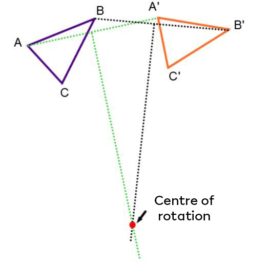
Here are the steps for solving a problem where the centre of rotation must be found by analyzing the initial and image figures:
-
Connect the corresponding points (A’ with A, B’ with B, etc.).
-
Draw the perpendicular bisectors of the segments formed.
-
Identify the intersection point of the perpendicular bisectors as the centre of rotation.
Here is an example of the process.
The centre of rotation below is located where the perpendicular bisectors of segments |\overline{AA’}| and |\overline{BB’}| intersect.
