A motion transmission system enables the transmission of rotational motion. The direction of rotation of different components, such as the driver component (or the driving unit), the intermediate component and the driven component (or receiving unit), can vary from one part to another.
It is possible to determine the direction of rotation of the components in a mechanism based on the type of system and its configuration.
-
The direction of rotation of a component is the direction of rotational motion relative to its axis of rotation. The direction of rotation can be clockwise or counterclockwise.
-
Clockwise rotation follows the same direction as the hands of a clock |(\circlearrowright).|
-
Counterclockwise rotation follows the direction opposite to the hands of a clock |(\circlearrowleft).|
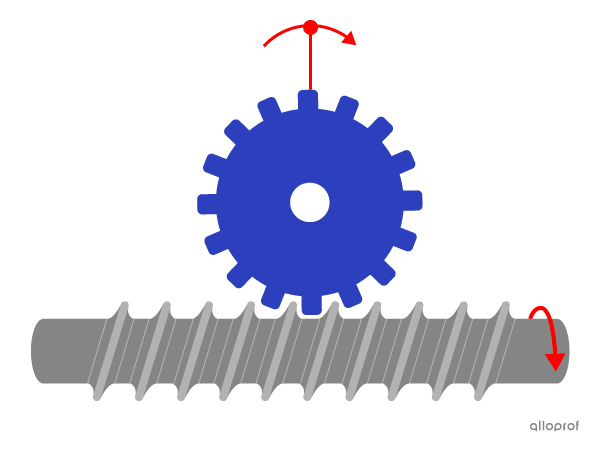
The worm and worm gear system alters the axis of rotation of the worm gear relative to the worm. In fact, the axis of rotation of the worm gear is perpendicular to the worm. Since the axes of the rotational motions are not parallel, their directions of rotation cannot be compared.
Similarly, the direction of rotation of components cannot be compared in perpendicular friction gear systems, bevel gear systems and belt and pulley systems that alter the axis of rotation from one component.
In a friction gear system or a gear assembly (also called gear trains), the direction of rotation alternates from one gear to another.
The direction of rotation of the driver and driven components in these systems can be determined using the following rules.
-
When the number of wheels in a system without belts or chains is even, the direction of rotation of the driver component is opposite to the driven component.
-
When the number of wheels in a system without belts or chains is odd, the direction of rotation of the driver component is identical to the driven component.
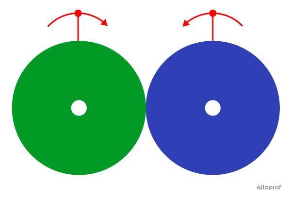
Here is a system made of two friction gears, which is an even number of wheels. The driver component rotates clockwise while the driven component rotates counterclockwise. The direction of rotation of the driver component is opposite to the driven component.
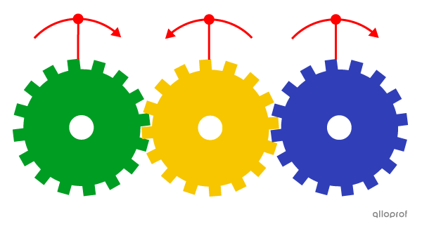
Here is a system made of three wheel gears, which is an odd number of wheels. The driver component rotates clockwise, the intermediate component rotates counterclockwise and the driven component rotates clockwise. The direction of rotation of the driver component is identical to the driven component.
In a belt and pulley system or a chain and sprocket system, the direction of rotation of the pulleys and sprockets is determined by their position relative to the belt or the chain.
The direction of rotation of the driver and the driven components in these systems can be determined using the following rules.
-
The direction of rotation of the pulleys and sprockets positioned on the same side of the belt or chain is identical.
-
The direction of rotation of the pulleys and sprockets positioned on the opposite sides of the belt or chain is opposite to each other.
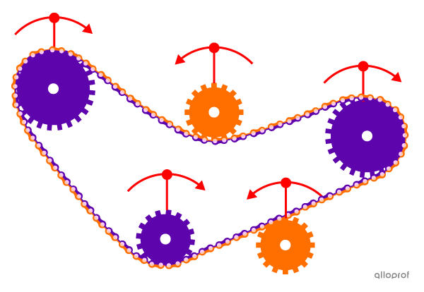
In this chain and sprocket system, all the sprockets positioned inside the chain rotate in the same direction (clockwise), while all the sprockets positioned outside the chain rotate in the opposite direction (counterclockwise).
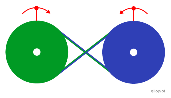
In a belt and pulley system, the belt can be crossed. In this case, unlike in the previous example, the pulleys positioned inside the belt are not touching the same surface of the belt. Therefore, the directions of rotation of the driver and driven components are opposite to each other.
In this belt and pulley system, the belt is crossed. The driver pulley rotates clockwise. Since the belt is crossed, the two pulleys are not touching the same surface of the belt. The driven pulley rotates in the direction opposite to the driver pulley (i.e., counterclockwise).
