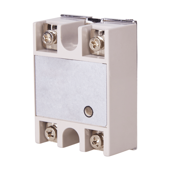
A relay is a control device that opens and closes an electrical circuit in response to a signal from another electrical circuit nearby.
Relays are generally used to control a device connected to a high-voltage circuit, called the power circuit, through a low-voltage circuit called the control circuit. The control and power circuits are not in direct contact with each other.

To turn on the appliance, the switch in the control circuit must be closed. The relay emits a signal which closes the power circuit. Once the current is flowing in the power circuit, the device is on.
There are two types of relays: electromagnetic and solid-state.
An electromagnetic relay has two main parts: an electromagnet connected to the control circuit and a switch connected to the power circuit.
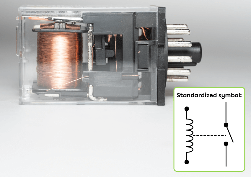
Source: Adapted from Wongsakorn Napaeng, Shutterstock.com
In an electromagnetic relay, the interaction between the fixed electromagnet of the control circuit and the movable pivot magnet opens and closes the switch of the power circuit. The following two images describe how this type of relay works.
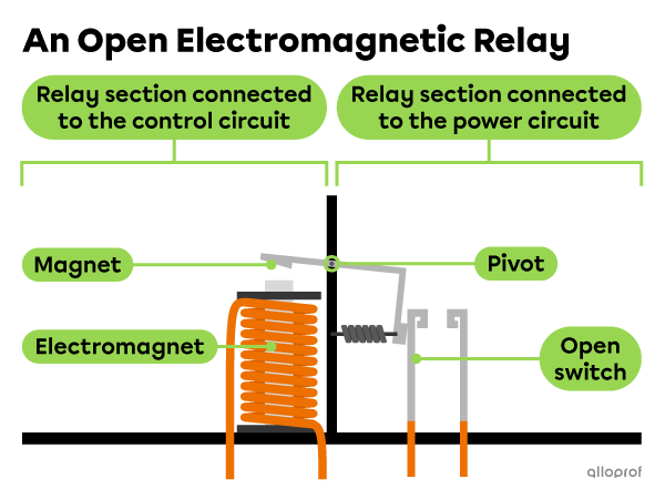
When there is no current flowing through the control circuit, the electromagnet does not attract the pivot magnet. The power circuit switch is open, so the device powered by this circuit is off.
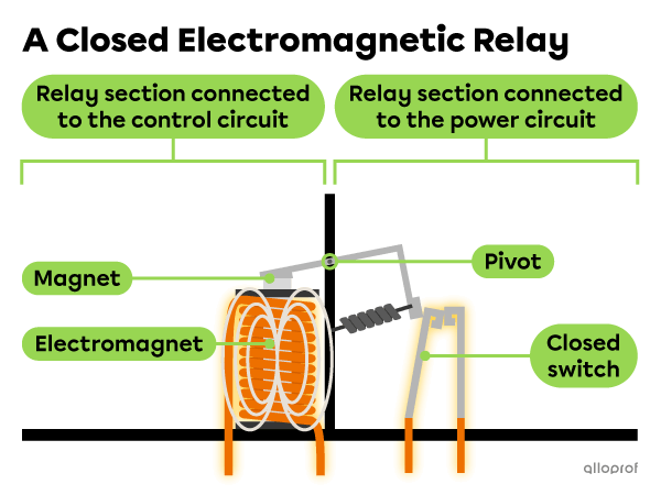
When current flows through the control circuit, the electromagnet generates a magnetic field which attracts the pivot magnet. The movement of the magnet at the pivot closes the switch of the power circuit switch and the device turns on.
The following electrical diagram shows the circuits with an audible warning device controlled by a relay.
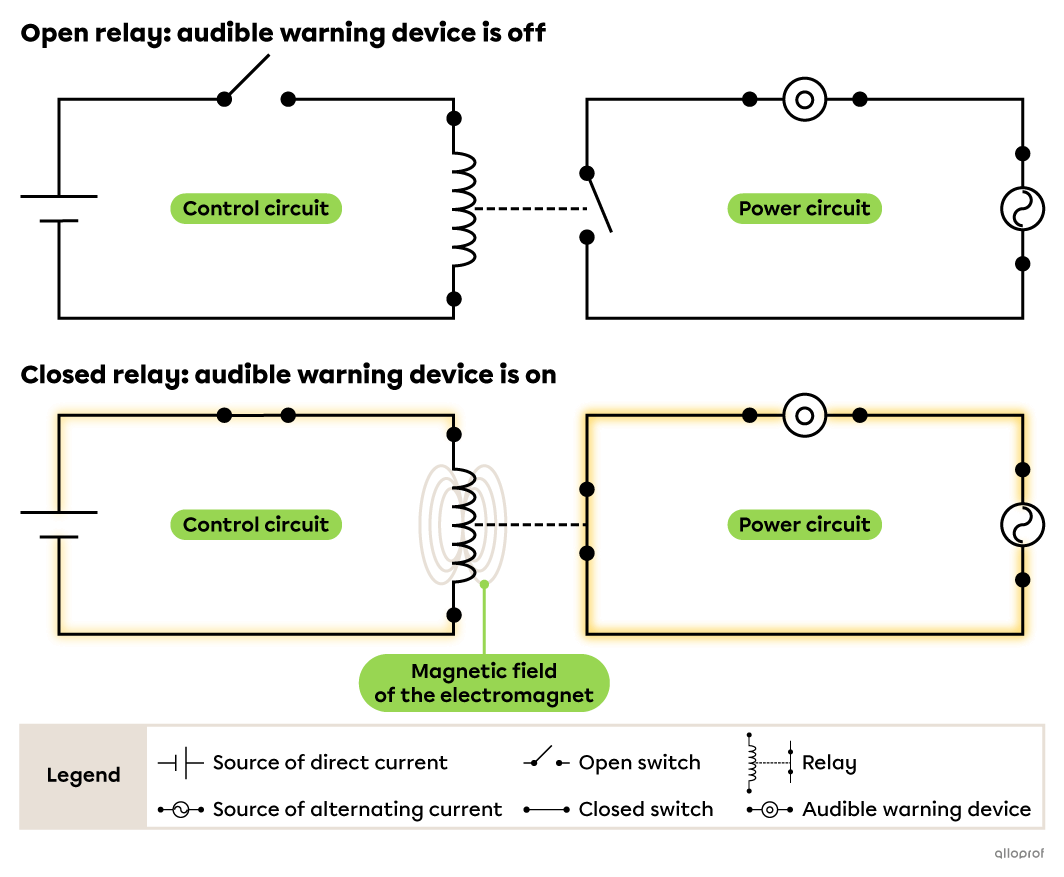
When the control circuit switch is open, no current flows through the relay’s electromagnet. The power circuit switch is therefore also open and the audible warning device is off.
When the control circuit switch is closed, current flows through the relay's electromagnet. The electromagnet's magnetic field causes the power circuit switch to close and the audible warning device to turn on.
Relays are used to control various devices, including some car components, such as the headlights.
The control circuit is in the cabin, where the driver can close the switch manually. The power circuit supplies electrical current to the headlights when current flows through the relay.
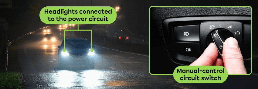
Sources: Adapted from Montypeter, Shutterstock.com and from Natallia Ploskaya, Shutterstock.com
Solid-state relays (SSRs) are sometimes called semiconductor relays. In this type of relay, the control circuit contains a light-emitting diode (LED) and the power circuit contains a photosensitive sensor that detects light. The sensor is usually made from silicon, a metalloid semiconductor.
In a solid-state relay, the interaction between the LED and the photosensor opens or closes the power circuit. The following two images describe how this type of relay works.
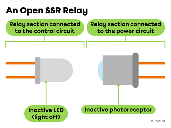
When there is no current flowing in the control circuit, the LED is off. The photosensor in the power circuit is inactive, which prevents the current from flowing. The device powered by this circuit is off.
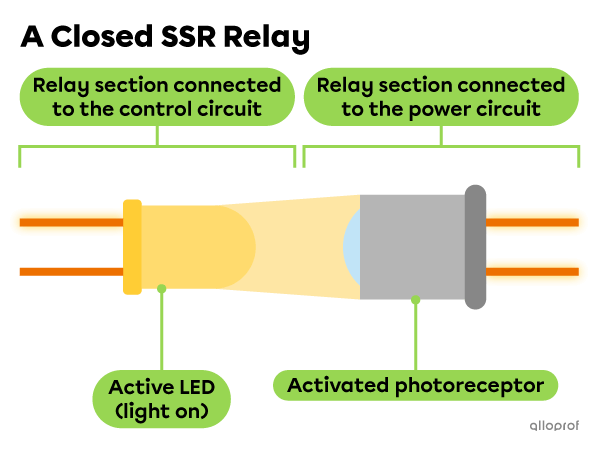
When current flows through the control circuit, the LED lights up. The photosensor in the power circuit is activated by the light, which enables current to flow. The device powered by this circuit turns on.
Unlike electromagnetic relays, semiconductor relays have no moving mechanical parts. They are therefore less susceptible to mechanical wear, and the operation is not affected by vibrations.
