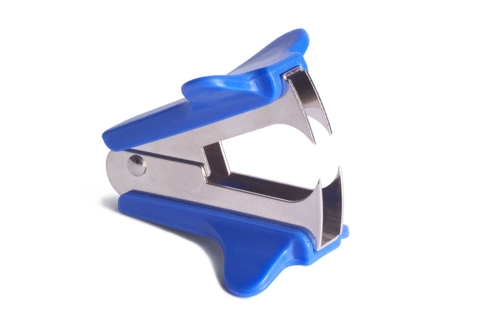
Before starting to manufacture a technical object, first make a list of needs and requirements in a specifications. Draw a first sketch of the general appearance of the object in an ideas document. Next, draw the design plan.
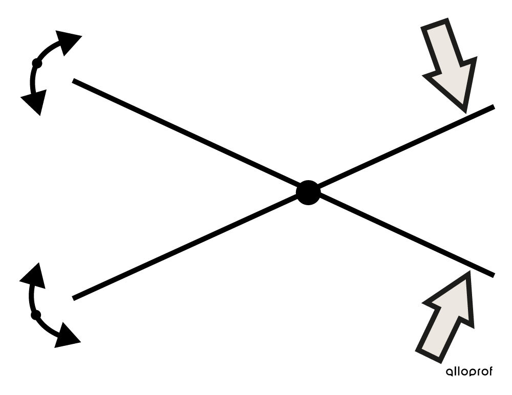
The design plan allows engineers to explain the detailed operation of the object to be built. This illustrates all the forces that can be exerted on the object, as well as all the movements that could be generated by these forces. The graphic representation of these forces and movements provides more visual insight than a simple written list.
A design plan usually includes the following elements:
- a simplified representation of the parts involved in the operation of the technical object;
- the force or forces allowing the object to function;
- the movements of the parts that result from these forces;
- the links useful for understanding how the object operates, if necessary.
Simple lines and different colours are used to differentiate the parts of the object. In addition, standardized symbols provide a simple and efficient manner to indicate forces, movements and connections. Finally, the design plan is often represented by a multi-view projection where one or more views are illustrated.


Kozak Sergii, Shutterstock.com


ajt, Shutterstock.com
Dumont, I., Meyer, É., Paul, D., Pomerleau, F. et Roy, V. (2019). Origine, cahier d'apprentissage 2, (2e ed.) [Manuel de l’élève]. Les Éditions CEC.