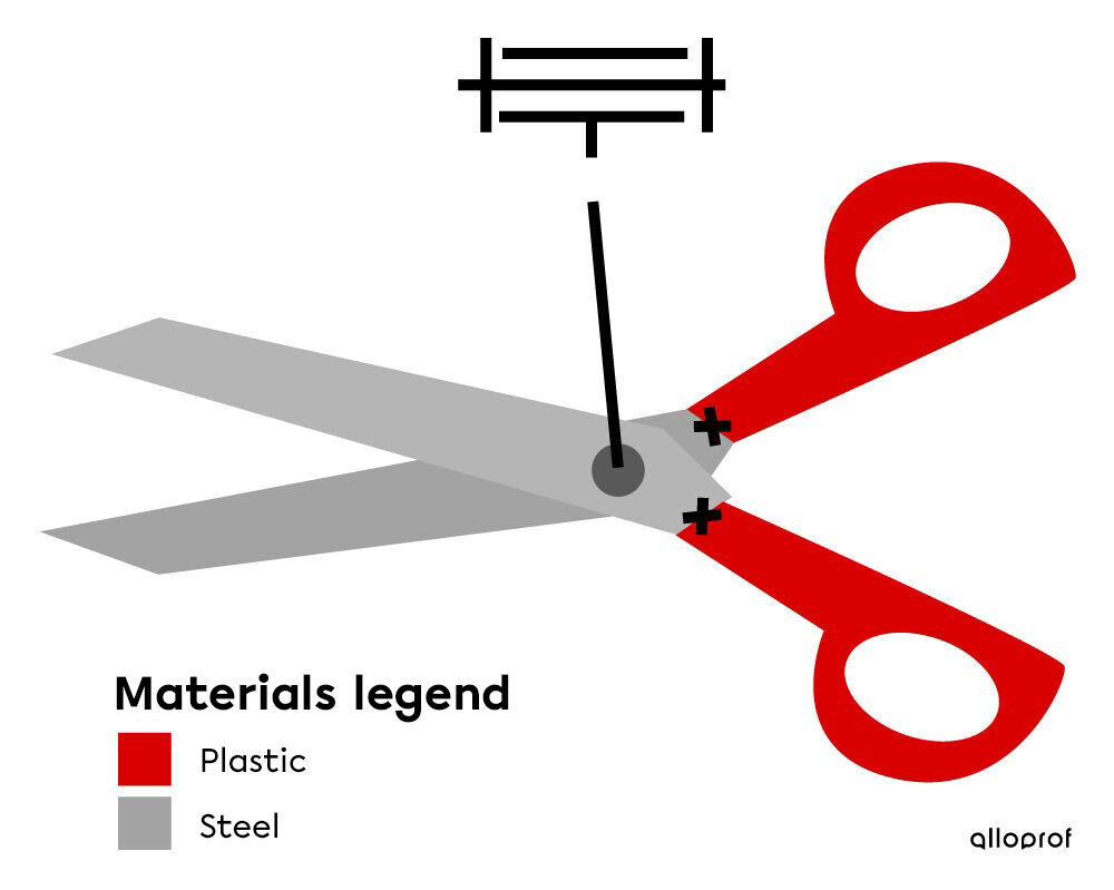
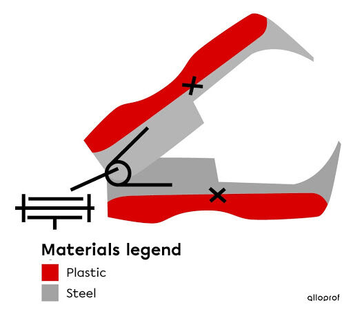
A technical diagram, also called a construction diagram, is a simplified drawing that represents the parts and materials used to manufacture a technical object. It contains information on the construction of parts, links, and guides.
Before starting to manufacture a technical object, first create a list of needs and requirements in a specifications document and make a first sketch of the general appearance of the object in an ideas document. Now, draw the design plan to represent the operation of the object. The next step is to make the technical diagram, which includes information needed to manufacture the various parts.
A technical diagram allows engineers to provide precise information concerning the different parts needed to manufacture an object. It is thus possible to plan for the materials to be used and the way of arranging them. A technical diagram can represent the whole object or simply part of it to explain a particular element.
A technical diagram usually includes the following elements:
- the components (parts) forming the technical object represented with different colours;
- the names of the components;
- the materials;
- linking and/or guiding units;
- the dimensions of the parts if necessary.
Different colours are used to differentiate the parts of an object. As well, standardized symbols make it possible to indicate links and guiding controls in a simple and efficient manner. Finally, the technical diagram is often represented by a multiview projection, where one or more views are illustrated.


Kozak Sergii, Shutterstock.com

