The control of parts makes it possible to verify the conformity or the quality of a part to the requirements described in the manufacturing process sheet. Controls are carried out not only during, but also after the part’s manufacturing process. Following the control, a part can be approved, reworked, or rejected. When inspecting a part, elements that can be examined are the flatness (without bends or twists) of a surface, the measure of an angle, a dimension, etc.
The control of the part’s dimension is done by direct measurement or by indirect measurement.
Direct measurement consists of evaluating, with a measuring tool, whether the actual dimensions of a part correspond to the ones in the detail drawing.
The person in charge of the control uses various tools for direct measurement, such as a ruler, digital caliper, or a three-dimensional measuring machine.
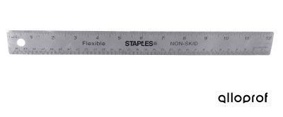
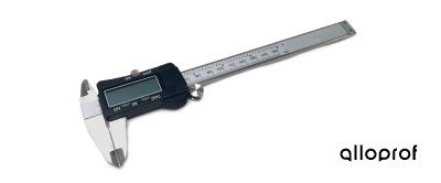
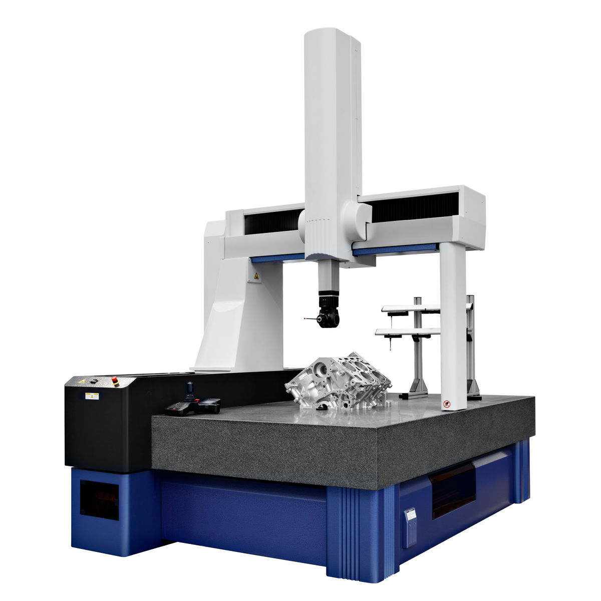
Matveev Aleksandr, Shutterstock.com
The choice of the measuring tool is based on the degree of accuracy required. Calipers (vernier caliper, digital caliper, etc.) are more accurate than rulers. A caliper can measure the distance between two external faces, the internal diameter, or even the depth of a hole. The coordinate measuring machine is even more accurate.
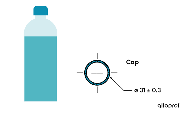
During inspection, the direct measurement of a part is compared to the one specified in the technical drawing. When comparing, the dimensional tolerance of the part must be taken into account.
The following illustration shows the control of the diameter of three caps (A, B, and C) by direct measurement with a vernier caliper.
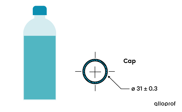
According to the dimensional tolerance of the detail drawing |(\text{DIA}\ 31.0 \pm0.3),| all diameter measurements included between |30.7\ \text{mm}| and |31.3\ \text{mm}| are accepted. Caps that are too small are rejected. Caps that are too large are sent back to be modified.
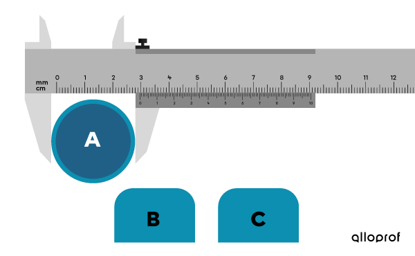
| Cap | Direct measurement |(\text{mm})| | Decision - Comment |
|---|---|---|
| A | |29.5| | Rejected - cap too small |
| B | |31.1| | Accepted |
| C | |31.6| | Sent back to be reworked - cap too big |
Indirect measurement consists of assessing, with a measuring tool, whether the dimensions of a part are within an acceptable range of values.
Control by indirect measurement is simple and fast. It makes it easy to sort accepted and rejected parts. This method does not give a numerical value to the size of the part. The person in charge of the control uses various indirect measuring tools such as the square, the level, and limit snap gauges.
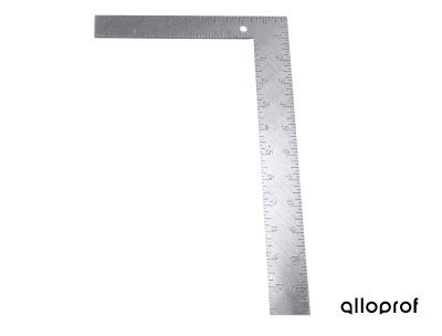
The square is used to control the perpendicularity of a part.
The level can be used to verify the horizontality or the verticality of a part.

imstock, Shutterstock.com
Limit snap gauges are used to verify the dimensions of a part.
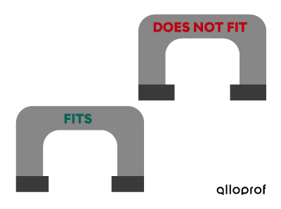
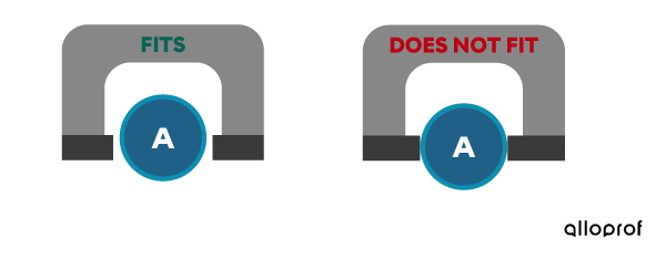
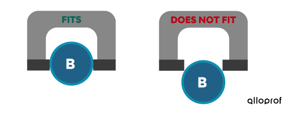
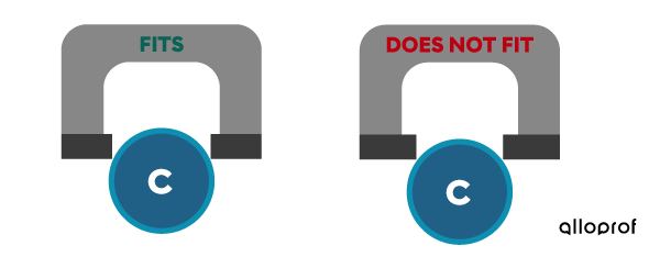
The following illustration shows the control of the diameter of three caps (A, B, and C) by indirect measurement with limit snap gauges.
For control, we use a:
-
limit snap gauge where the cap must fit (FITS);
if the cap doesn't fit, it means it is too big. -
limit snap gauge where the cap must not fit (DOES NOT FIT);
if the cap fits, it means it is too small.
A cap is accepted only if it complies with both limit snap gauges.
Cap A fits into both limit snap gauges.
Cap A is too small.
Cap B fits into the first gauge and does not fit into the second.
Cap B is accepted.
Cap C does not fit into either gauge.
Cap C is too big.
| Cap | Gauge FITS | Gauge DOES NOT FIT | Decision |
|---|---|---|---|
| A | Fits | Fits | Rejected |
| B | Fits | Does not fit | Accepted |
| C | Does not fit | Does not fit | Rejected |