The ministry exam in science includes a technological analysis of an object. This is part C of the exam.
In this concept sheet, you will find strategies for analyzing the video and 2D plans of the object, as well as tips for answering the questions.
To practice, try our technological analysis simulations!
The number of questions in the technological analysis section differs between the Science & Technology (ST) program and the Applied Science & Technology (AST) program.
| Science and Technology (ST) | Applied Science and Technology (ATS) | |
|---|---|---|
| Number of questions | 5 | 6 |
To complete the Ministry Exam’s technological analysis section the following tools are necessary:
- video animation of the technical object
- diagrams of the technical object
Proper preparation is essential for a successful technological analysis. To prepare, a thorough review of the technological world advisable.
Additionally, different strategies can help during the exam.
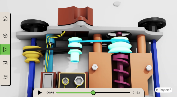
The animation of the technical object is a short video (approximately 3 min) that plays repeatedly during the exam. The animation shows the object from different perspectives and the following elements:
- overall function of the object;
- mechanical operation of the technical object;
- motion transmission and motion transformation systems;
- operation of the electrical circuit;
- characteristics of links between the components.
While watching the animation, is is important to focus on the following points:
-
interactions between the components;
-
association between the components in the video and the ones in the diagrams;
-
opening and closing of switches;
-
links between components.
Analyzing the interactions between the object’s components allows the student to identify the following:
-
motion transmission and transformation systems;
-
how mechanisms start up;
-
motions performed by the components.
The motor drives the rotation of two belt and pulley systems. These are motion transmission mechanisms.
Establishing a connection between the components shown in the video and the ones in the diagrams can lead to a greater understanding of how the object functions.
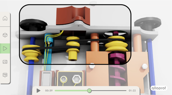
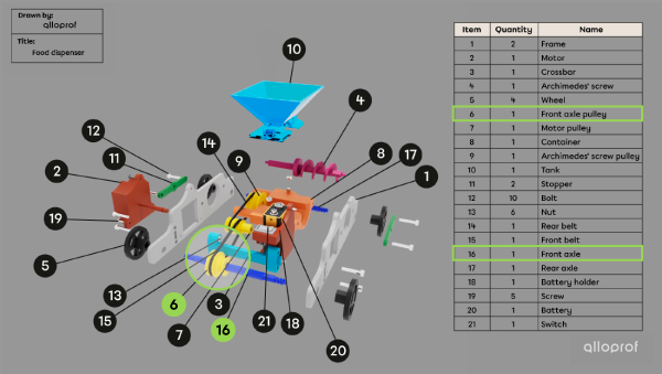
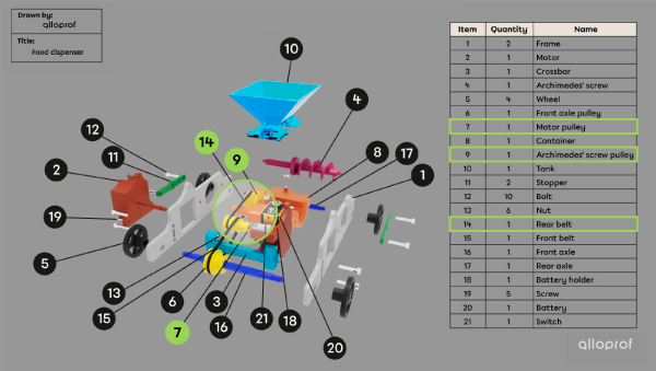
In this section of the video, the highlighted components are the motor pulley (Item 7), the rear belt (Item 14) and the Archimedes screw pulley (Item 9). The components can be found in the table, also called a parts list, in the complete exploded view.


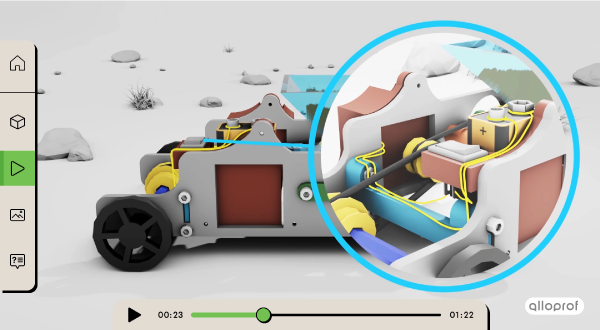
In the video, the flow of the electrical current within the circuit is generally indicated with yellow wires. Therefore, a section where a switch opens and closes enables students to identify the circuit and its electrical components. Furthermore, when the switch is closed, the yellow colour of the wires in a specific section of the circuit indicates the presence of a parallel circuit.
Here, the switch is open, so the electrical current is not flowing through the electrical components. The wires have their regular colours, either black or red. They are not highlighted in this section of the video.
The person is about to close the switch.
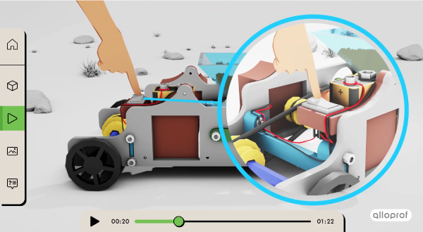
Here, the switch is closed, so the electrical current is flowing through the electrical components. The flow of electrical current in the circuit is indicated by the wire’s yellow colour. By locating the wires, the other components of the circuit can be identified, such as the motor and the battery.
In the video, the disassembly of the technical object is shown. The sequence is very useful to determine the properties of links. It also allows us to identify linking and guiding components, if necessary.
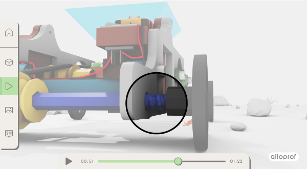
Watching the disassembly of the wheel and front axle, it can be determined that the link between them is removable.
The absence of a linking component and the threaded end of the axle indicates that the wheel is screwed on directly. It is a direct link.
Since the wheel is screwed onto the front axle, it cannot move freely relative to the axle. It is a complete link.
Finally, the hard plastic used to make the front axle and the wheel leads us to conclude that the link is rigid.
While watching the video, it is important to avoid all distractions. Do not hesitate to watch the video multiple times before answering the questions.
Some students prefer to answer the technological analysis questions at the beginning of the exam period, while others prefer to do it at the end.
When certain sections of the video are more difficult to understand, it is possible to return to them later.
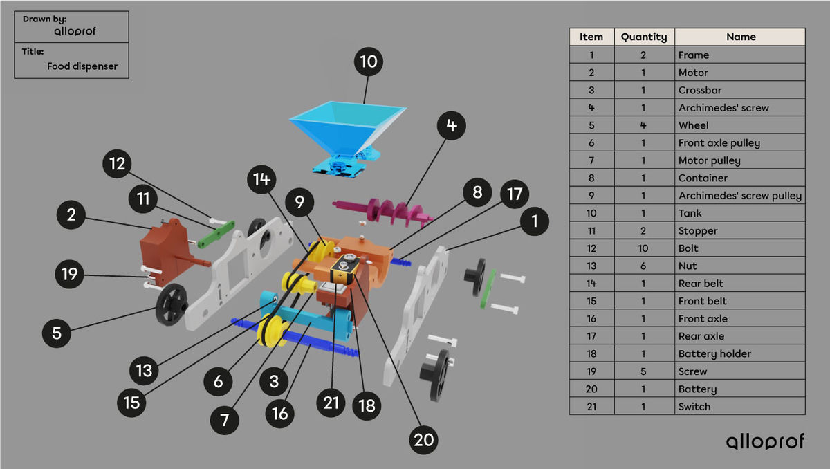
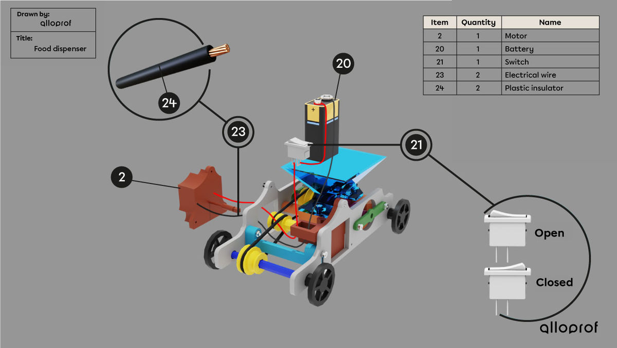
The diagrams of the technical object is in the Reference Document. Generally, the following information is included:
- a complete exploded view of the technical object along with the parts list shown as a table (item number, quantity of items, name);
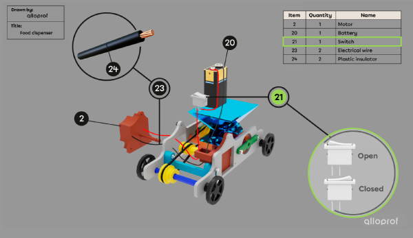
- a representation of an electrical circuit with its own parts list.
While reading the diagrams of the technical object, it is important to focus on the following points:
-
parts list (table);
-
the shape of the components;
-
component disassembly in the complete exploded view;
-
highlighted sections of the diagram.
The parts list is included in the 2D diagrams of the technical object. The table summarizes information about the different components of the object. For each component there is the item number, the quantity of items, and the name of the component.
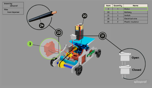
The representation of the electrical circuit highlights Item 2. By looking at the table, it can be concluded that Item 2 is a motor (name) and that there is only one motor (quantity) in the technical object.
The shape of the components can help identify the type of motion and the type of guiding.
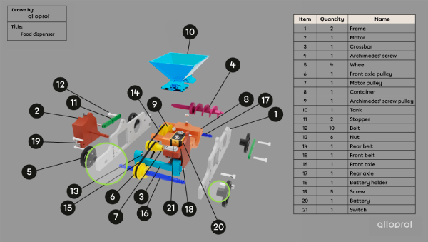
The complete exploded view shows a round opening in the frame. The round shape of the opening indicates rotational guiding of the wheel.
Additionally, the two wheels on each side of the front axle prevent it from undergoing translational guiding.
The complete exploded view indicates whether components can be disassembled or not, which allows the distinction between removable and permanent links.
In the complete exploded view, it is possible to see that the front axle pulley (Item 6) and the front axle (Item 16) are still attached. It can be concluded that the link is permanent.
On the diagrams, certain sections of the technical object can be highlighted. It is important to pay attention to the highlighted components. They are likely to be the subject of a question.
In the electrical circuit representation, the switch (Item 21) is highlighted with the specifications open and closed. A question about the switch or about the control function is likely.
After watching the video animation and analyzing the diagram of the object, it is time to answer the exam questions. It is important to read them carefully. An unanswered question does not earn any marks. Therefore, it is worth trying to answer every question.
While answering the questions, it is important to to focus on the following points:
- the components specified in the question
- the choice of terminology.
In each question, some components are identified. The answer should include their names and a clear explanation of how they interact with each other. Remember that it is impossible to obtain full marks if the answer does not take into account one of the components included in the question.
The task is to describe the interaction between the motor pulley (Item 7), the rear belt (Item 14), and the Archimedes screw pulley (Item 9).
Here, it should be written, “The rotational motion of the motor pulley drives the rotational motion of the rear belt and the Archimedes screw pulley.”
The following sentence would also be acceptable, “The rotational motion of the motor pulley drives the rotational motion of the Archimedes screw pulley with the rear belt acting as an intermediate unit.”
On the other hand, a sentence such as, “The rotational motion of the motor pulley drives the rotational motion of the Archimedes screw pulley,” would not be acceptable since the interaction with the rear belt is not described, even though it is identified in the question. Since part of the answer is missing, no marks would be given.
To answer the questions, it is absolutely crucial to use proper technological language.
The screenshot of the video shows a set of components that are featured. If the interaction between these components has to be described, the following sentence can be written, “The rotational motion of the motor pulley drives the rotational motion of the rear belt and the Archimedes screw pulley.”
Expressions such as “rotational motion” and “drives the rotational motion” are terms used in proper technological language.
Wording such as “The motor pulley spins the belt, which then makes the Archimedes screw pulley spin,” would not be acceptable. In fact, the word “spins” should not be used when describing interactions between components of a technical object.


Through the entire technological analysis of a technical object, the questions mainly rely on the mastery and/or application of the knowledge of the technological world.
The following lists include useful concepts for review.